The most important component of the profiler is the PAR sensor which is using to measure downwelling irradiance at the surface and through the water column. In order to measure downwelling irradiance the sensor must measure light across the entire upward looking hemisphere and the irradiance must be weighted by the cosine of the angle of incidence, according to Lambert’s Cosine law. Diffusers made from materials like acrylic, Teflon or plastic are commonly placed over the photodiode to achieve a cosine corrected response. Additionally, a filter is needed to get the correct spectral response (400-700 nm) from the sensor.

Diffusing disk
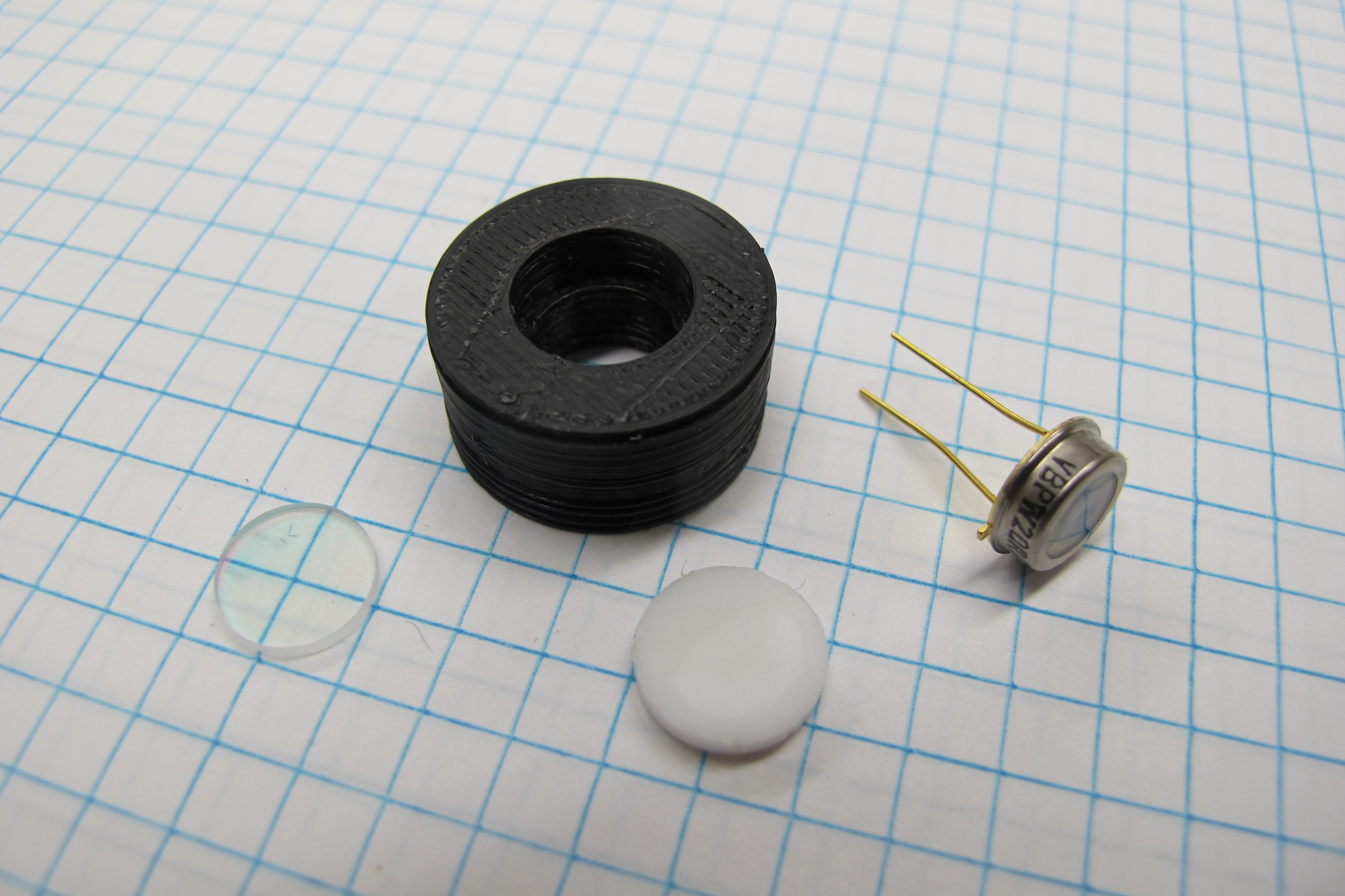
I cut the diffusing disk from a 2mm thick piece of PTFE using a cork borer which had an inner diameter of about 10mm. By rotating the borer while applying downward pressure I was able to get perfectly round disks. To get a clean cut its important the borer be sharp and held perpendicular to the sheet of PTFE.

Visible bandpass filter
The visible bandpass filter is an important part of the PAR sensor because it restricts the wavelengths of light reaching the photodiode to those used in photosynthesis (400-700 nm). I found some UV-IR cut filters on eBay for cheap and decided to try them out. Details about the spectral characteristics of the filters were sparse so I measured the transmissivity of the filters myself using a spectrometer.
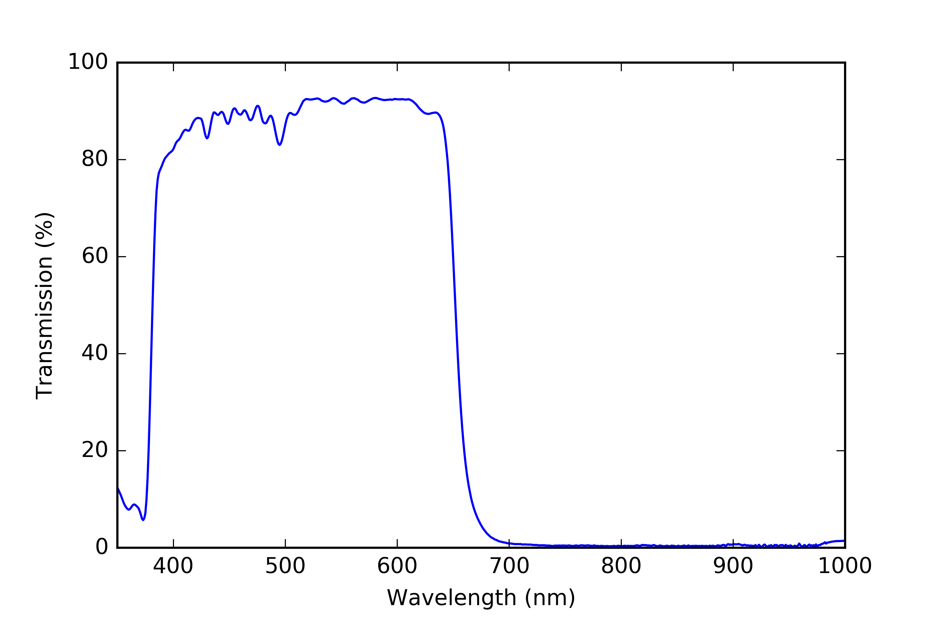
You can see the the filter cuts off a bit short of 700 nm which is not ideal but without spending a lot more money I don’t think I’ll be able to do any better, so for now I’m going to stick with them
Photodiode
I’m using a Vishay BPW 20 photodiode to measure the light levels in the PAR sensor it’s a cheap (~$6) sensor that has sensitivity between 375 – 1175 nm. For the purpose of testing the cosine response of the sensor I connected the photodiode to an amplifier circuit using CA3140EZ op amp. I will go into more detail about the op amp circuit in the next project log.
Testing
To test the cosine response, I set the sensor up on an optical bench at the base of a large arm with a solar lamp at the end. The arm was mounted to allow it to swing about its base and the angle of the arm relative to the surface of the cosine receptor was measured using a digital protractor.
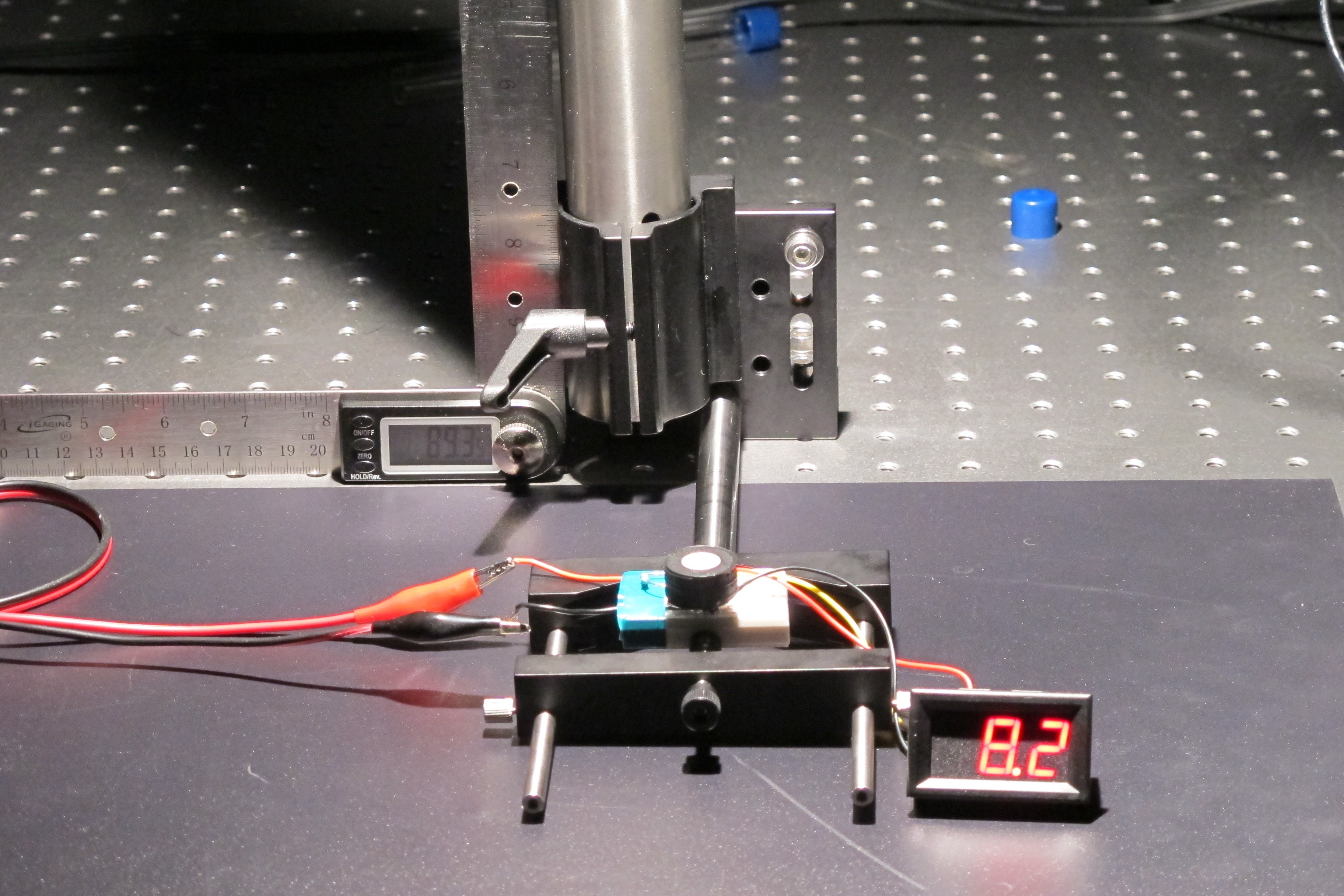
I the moved the lamp from directly above the sensor ( 0°) to perpendicular ( 90°) while recording the output voltage of the circuit at different angles along the way.

The figure below shows the measured response of the detector compared to that of an ideal cosine response. I was really happy will this outcome and don't think I can realistically do any better.
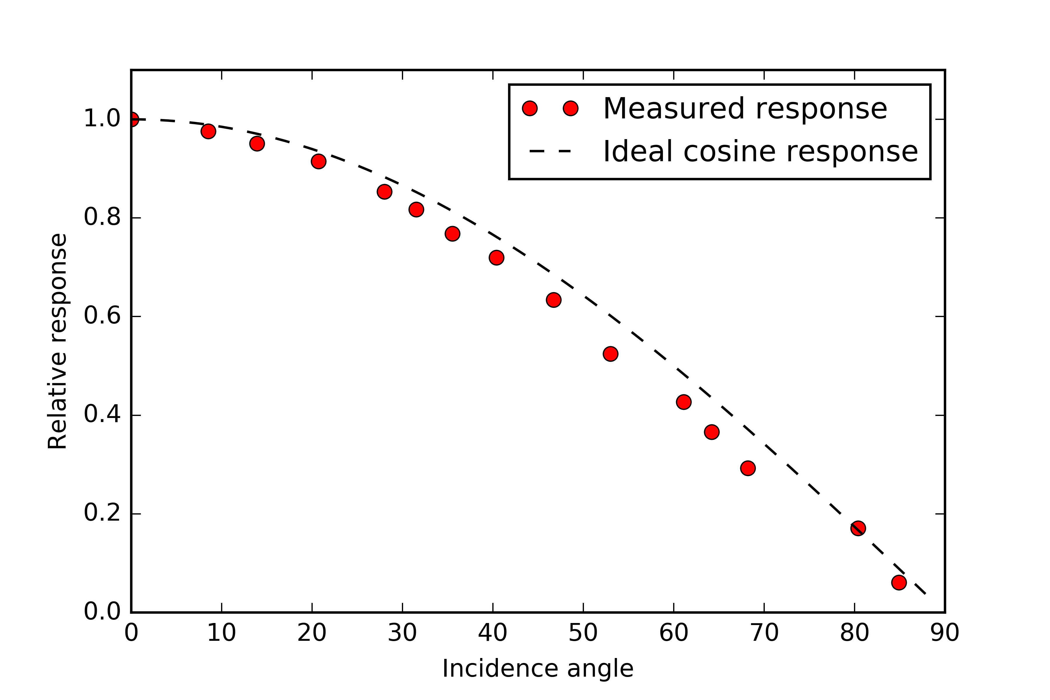
One difference to note between my design and that of commercially available sensors is that my diffuser is flush with the surface of the casing whereas normally you would see that the diffuser set a bit proud. The reason this is done is because at low incidence angles the diffusing material acts more like a specular reflector causing light to bounce off the surface rather than being transmitted through. By raising the diffuser a bit this loss is compensated for by light which enters the disc through the side wall. Sensors designed this way also have a raised rim around the diffuser to block any light parallel to the surface of the disc where the incidence angle is 90° and the irradiance on the surface should be zero (cosine(90°) = 0).
Discussions
Become a Hackaday.io Member
Create an account to leave a comment. Already have an account? Log In.