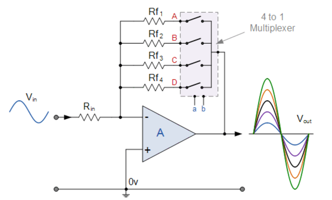
I haven’t yet gone over the design of the circuit for the profiler yet but hope to get to it in a few days. Generally, it’ll be based around and Arduino Uno with a custom shield that will contain components to drive the LEDs, amplify the signal from the photodiodes, and so forth. One of the components is the op amp that will be used to convert the current generated by the photodiode to a voltage. Because the light levels will be variable at both the surface and throughout the water column I need to be able to adjust the gain of the sensor without actually changing the feedback resistor. I initially considered using a digital potentiometer to adjust the gain but found that the high resistance values needed for the op-amp (Mohm – Gohm range) made this challenging as most digital pots max out at around 1 Mohm, furthermore the tolerances are generally unacceptably high (~30%). I came across an op amp circuit here where a multiplexer was used to switch between different feedback resistors and decided to give it a try.
After initial success on a breadboard
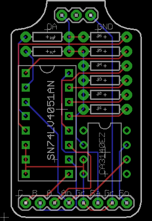
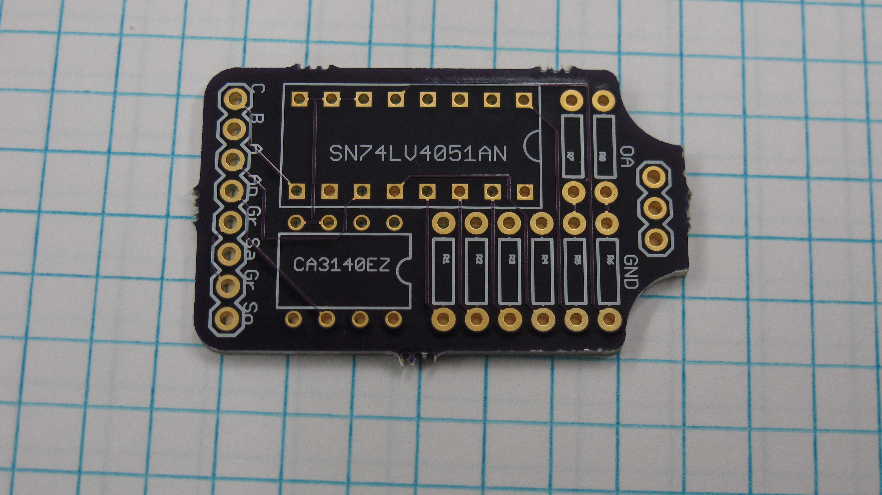
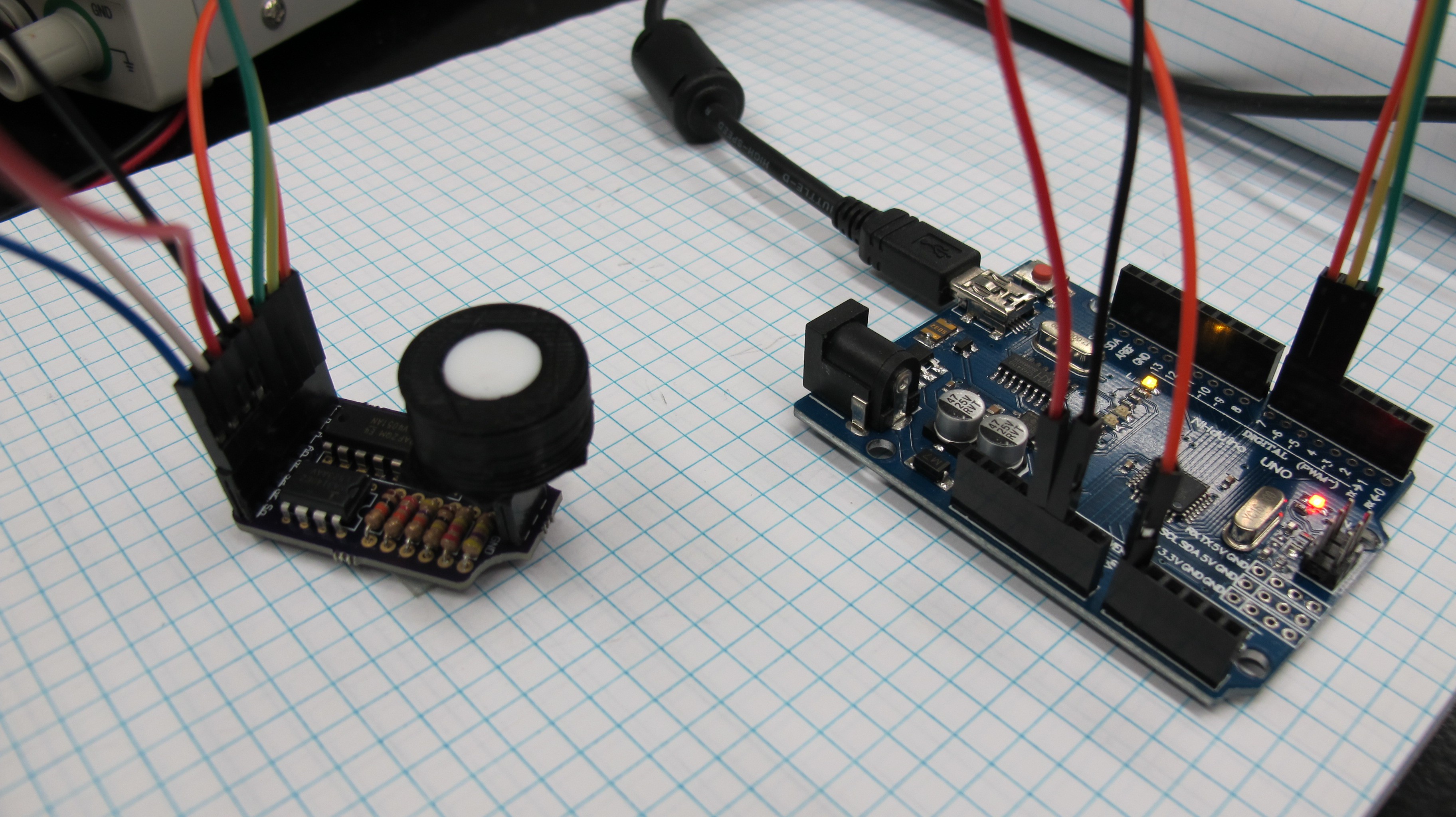
I designed a PCB in Eagle to do some further testing. The circuit uses an 8
channel SN74LV4051AN mux and a CA3140EZ op-amp giving me 8 different gain values. The mux
is powered by the 5v line from the Arduino, while the op amp is powered by an
external power source.
The 3 pins at the top of the circuits are for a header to connect the photodiode, the photodiode only has two leads while the header was designed to accommodate the space between them. Pins A-C connect to the selector line of the mux and are set by 3 digital pins on the Arduino.
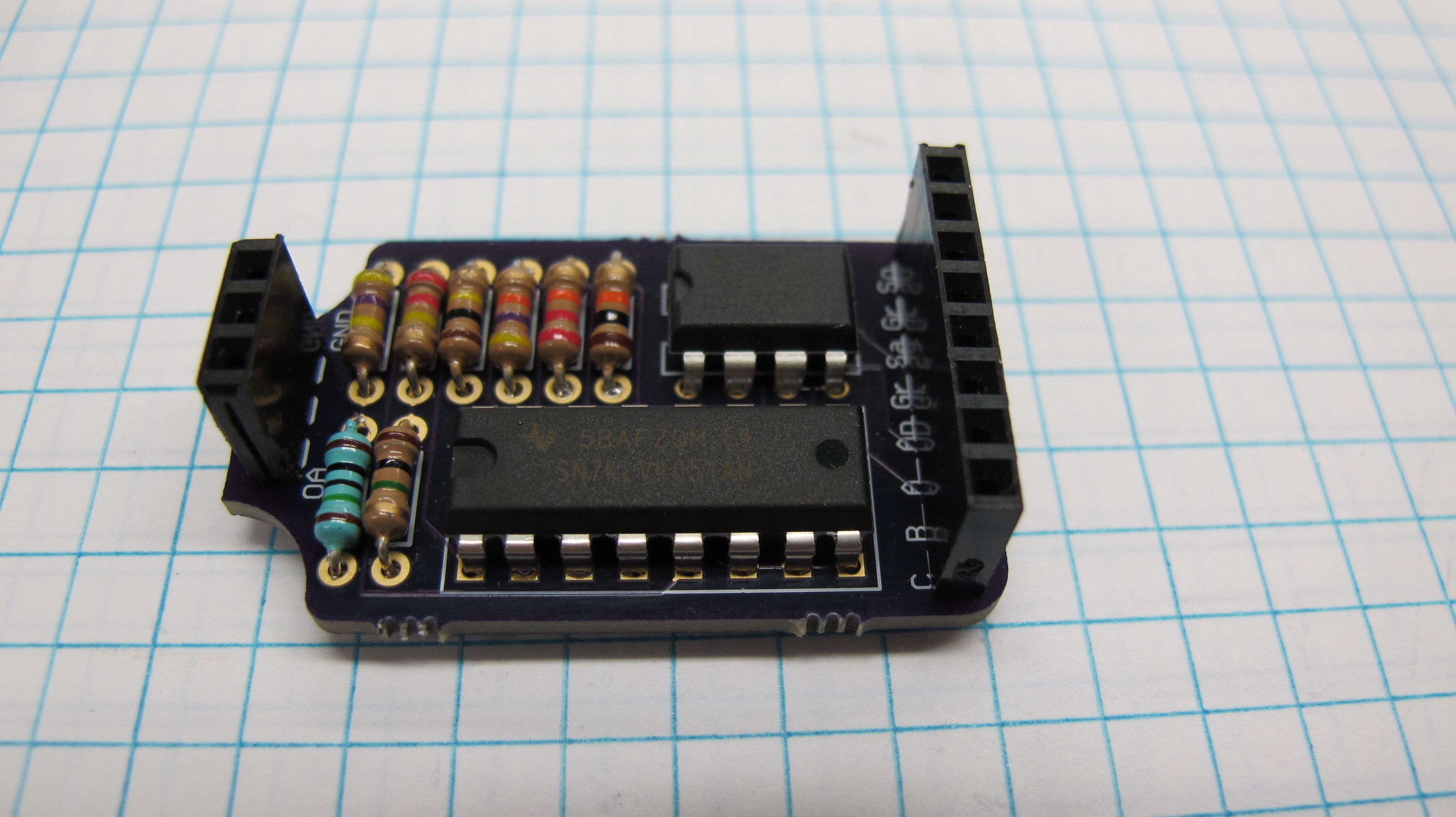
Currently I don't have any feedback capacitors in the circuit and didn't specifically design it to accommodate them but I will need them and figure for the time being I can just solder them in parallel with the resistors as the holes are large enough to fit both the capacitor and resistor pins. One of the reasons I have not done so yet is that I am unsure of the values to use, and for testing purposes now the circuit seems to work reasonably well.
Testing
More to come.........
Discussions
Become a Hackaday.io Member
Create an account to leave a comment. Already have an account? Log In.