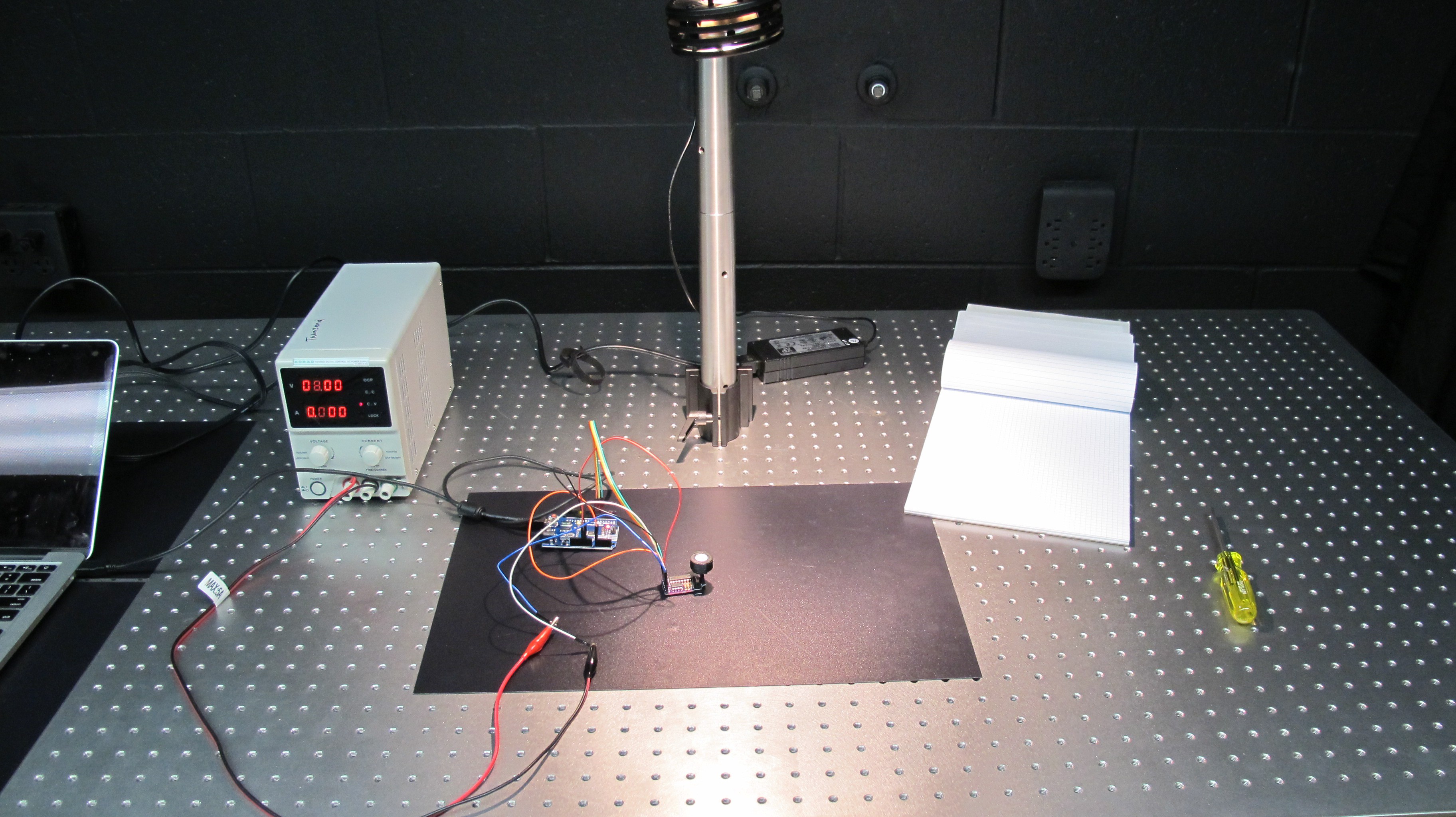
To test whether the variable gain circuit
was working properly I placed the PAR sensor under a light and programmed the
Arduino to continuously cycle through the each of the feedback resistors and
read the resultant voltage. I did this under different light levels by moving
the lamp progressively closer to the sensor. At each light level I recorded the
DN associated with each feedback resistor. If the circuit is working correctly
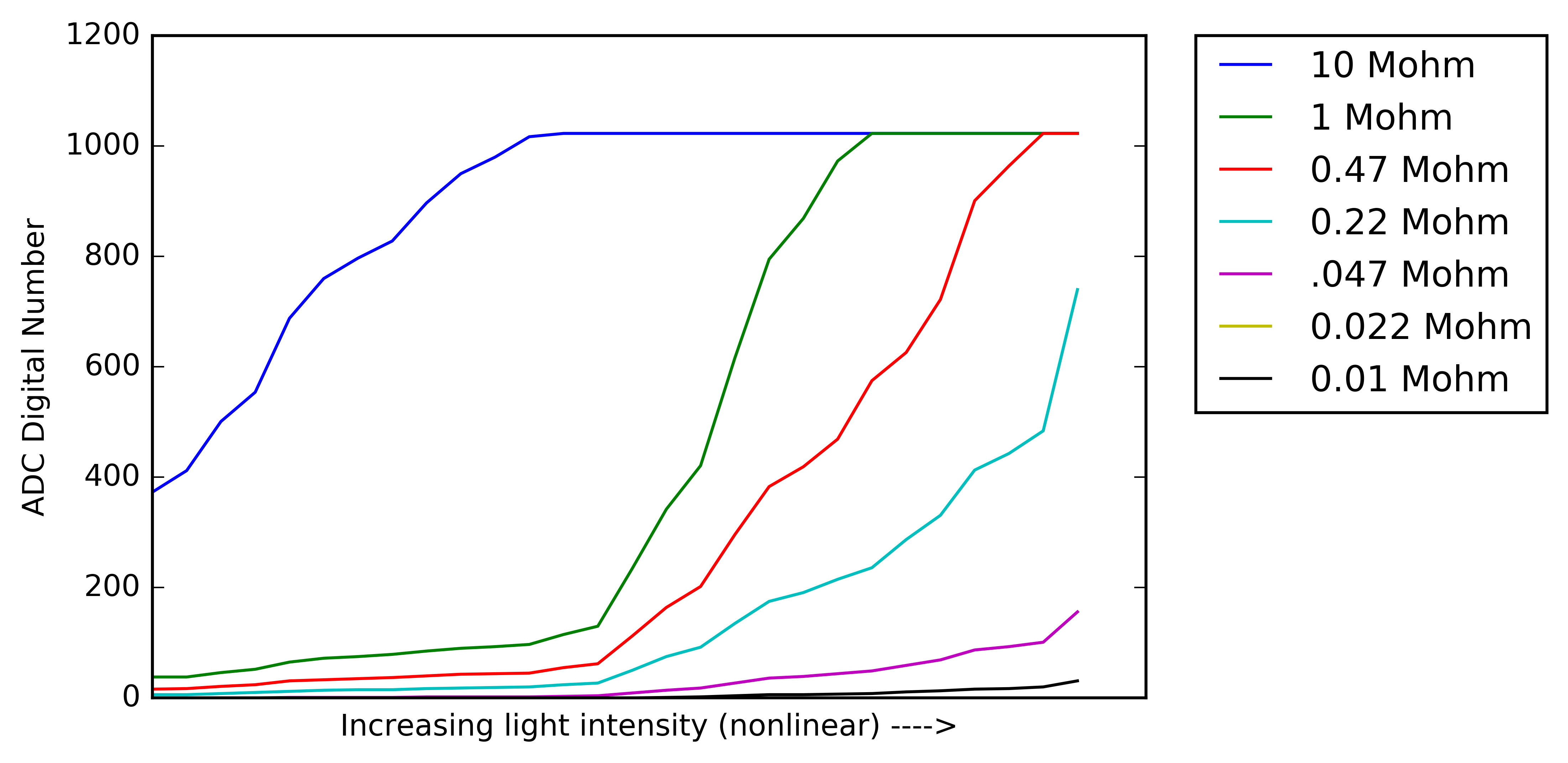
then the ratio of the outputs from two differently valued feedback resistors
should be the same as the ratio of their resistances. Ex. The output of a 1 MOhm feedback resistor should be 1/10th of the output using a 10 MOhm resistor, +/- their tolerances.
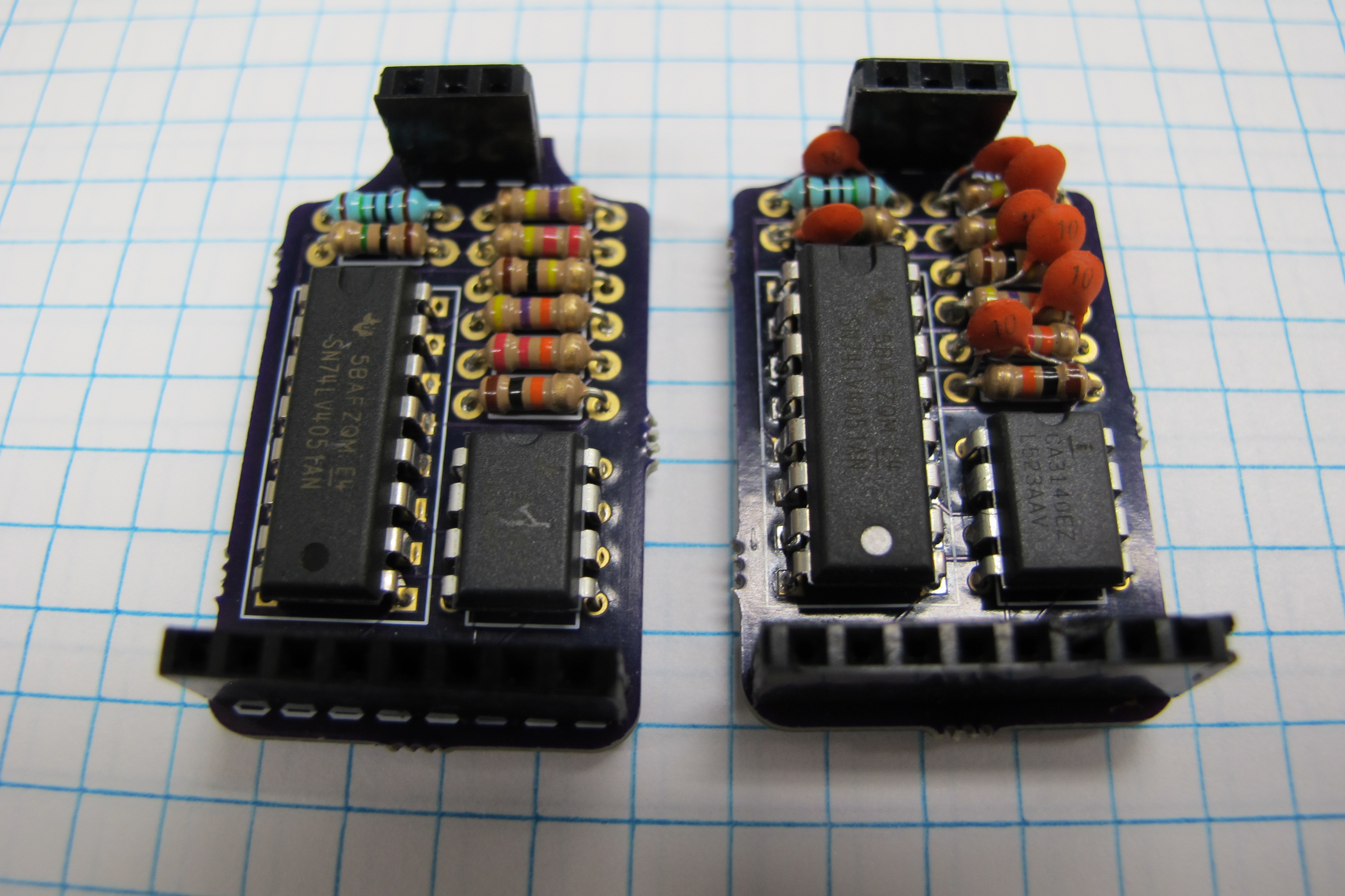
I did the initial set of tests on the op amp circuit without feedback capacitors and found that at high light levels the large feedback resistors (10 and 1 MOhms) resulted in wildly oscillating values. To try and remedy this
I went ahead and soldered up
another board this time with a 10 pF capacitor in parallel with each of the
feedback resistors, which seemed to solve the problem. The picture below shows a both mux circuits with and without the feedback capacitors.
The figure below shows the output of the op-amp for each of the feedback resistors along the light level gradient. One thing to note is that for the 22kOhm resistor there is no data, for some reason it wasn't working correctly I think I messed the resistor up or the mux pin connected to it while soldering the circuit. You can seen that after a certain light intensity the feedback resistors saturate which makes having multiple resistors very valuable, same for the opposite effect at low light levels where there is no/very little response.
Discussions
Become a Hackaday.io Member
Create an account to leave a comment. Already have an account? Log In.