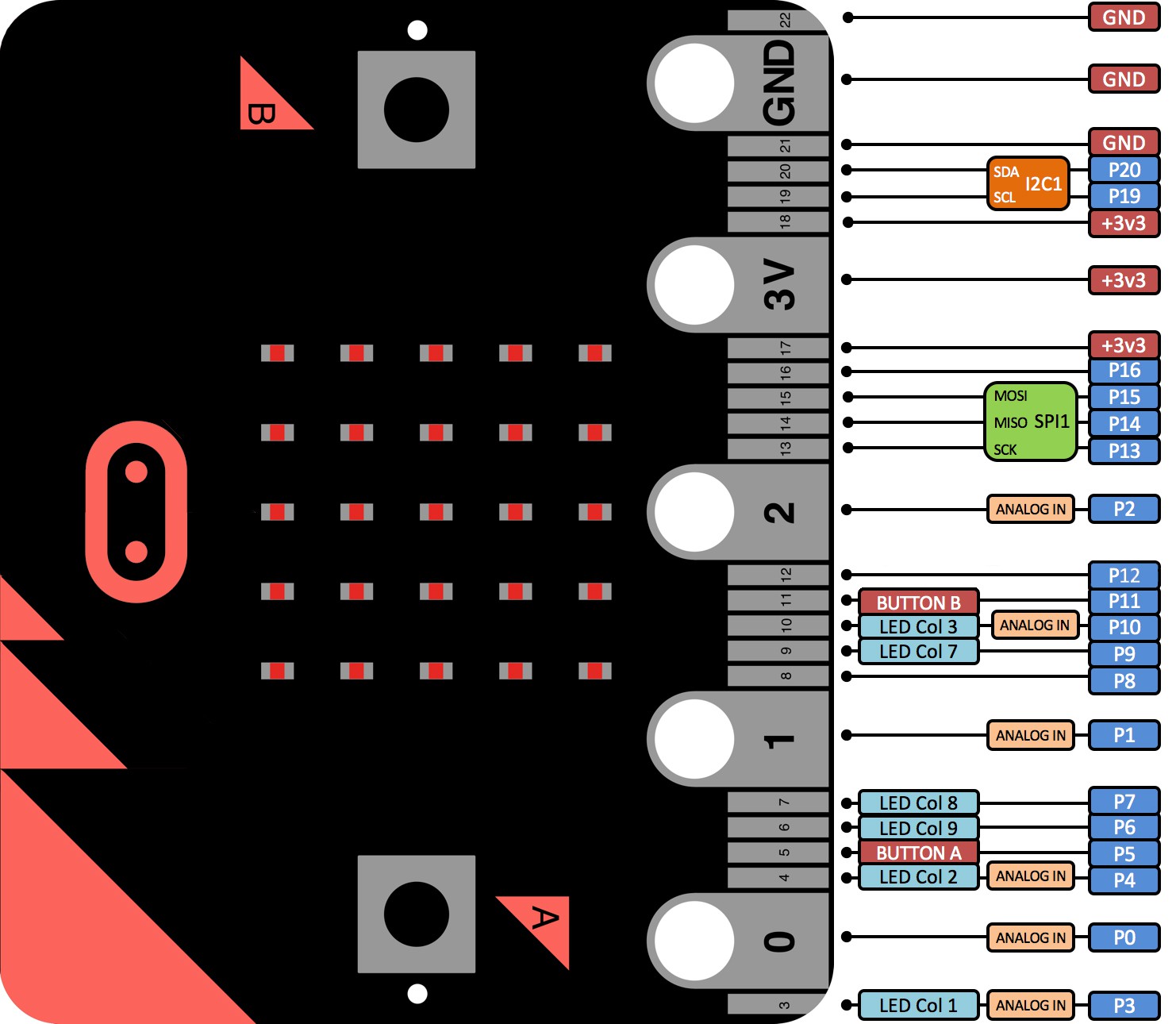
The BBC Micro:Bit is an IOT microprocessor board based on the Nordic Semiconductor NRF51822 chip with an ARM Cortex M0 processor and bluetooth. For this project it was decided to program the board using the micropython development environment.
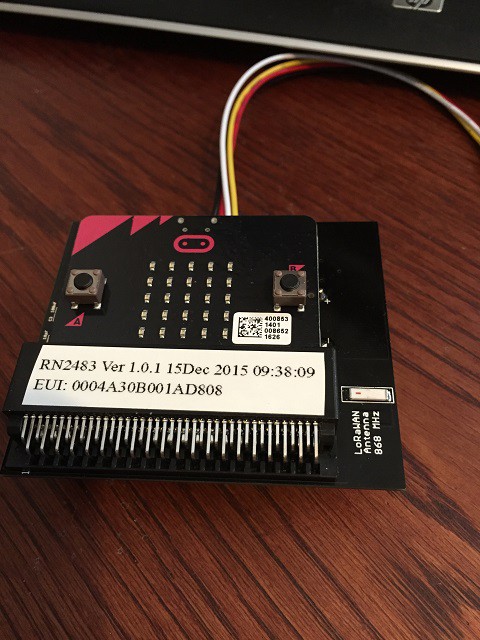
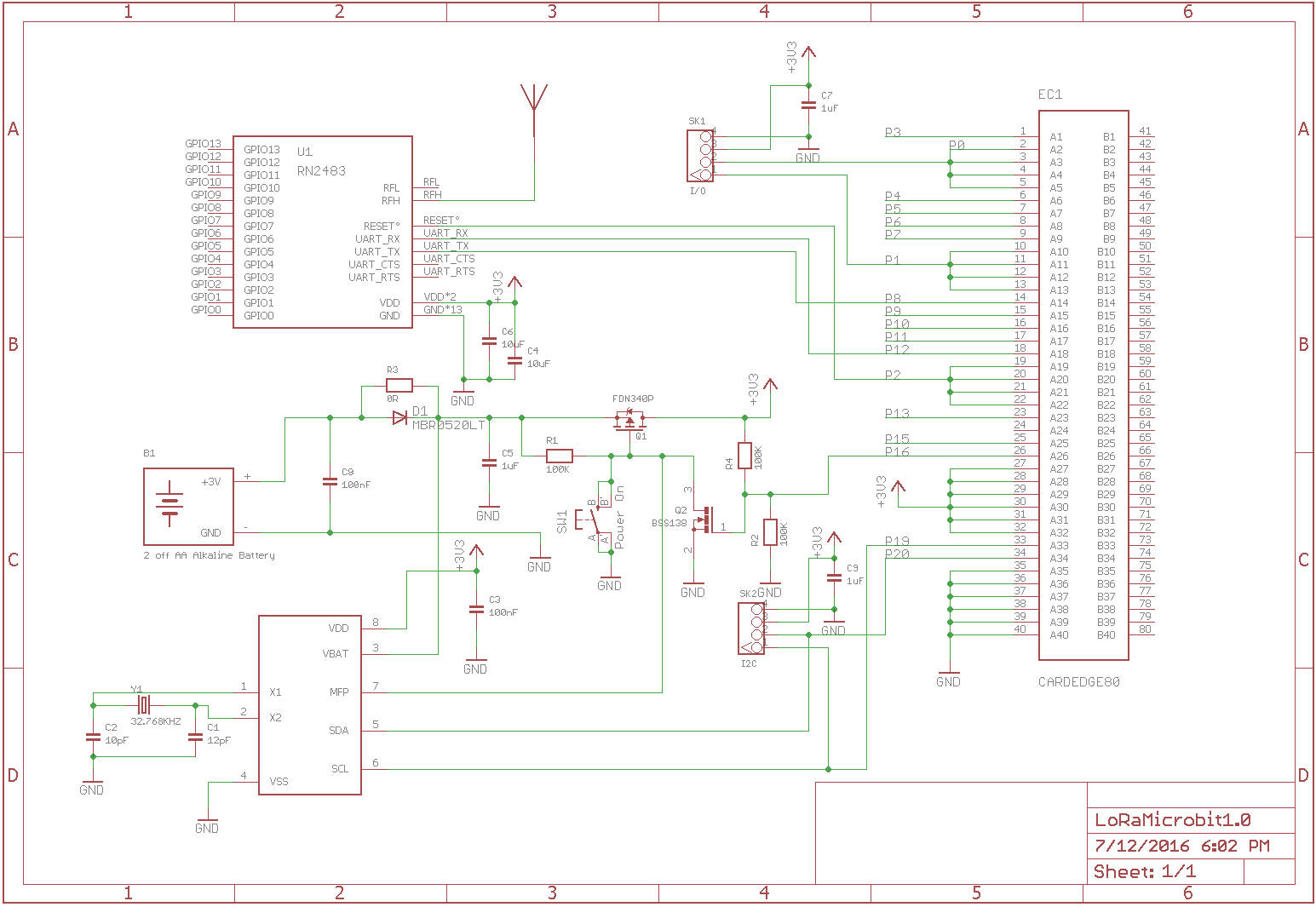
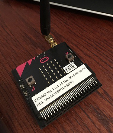
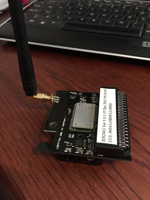
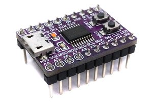
The LoRaWAN radio module used to connect to the TTN is the RN2483 from Microchip. This module connects to the Micro:Bit over a serial interface. A microcontroller integral to the RN2483 take care of all the processing for the radio and supports the LoRaWAN protocol layers. In this build the RN2483 module is mounted on a breakout board from Azzy's Electronics Store on Tindie.
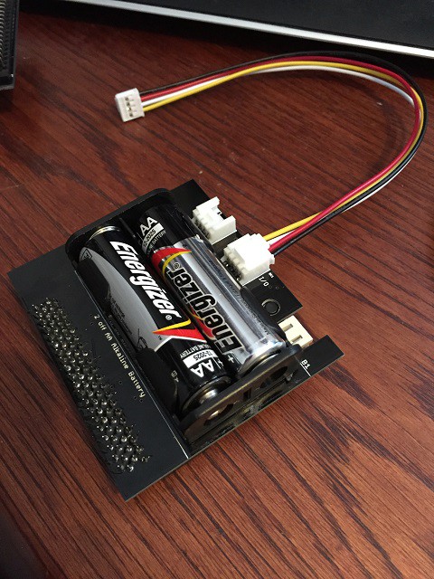
The Radio module is powered from the Micro:Bit using either USB or battery. Three data lines between the Micro:Bit and radio module carry a hardware reset line and serial transmit and receive data.
The Micro:Bit only has a single serial port and this is redirected to the I/O pins of the board. This means that the python console is no longer available, but does not interfere with the ability to program the Micro:Bit. Unfortunately the bluetooth interface on the Micro:Bit is not available when using python.
The python code initializes the radio over the serial connection and sends data packets over the radio channel. The antenna for the 868 MHz radio in this case is a short piece of wire of the correct length (82mm).
The Things Network (TTN) comprises a number of internet connected LoRaWAN gateways deployed by enthusiastic supporters in a growing number of areas around the world. If you don't already have local coverage, then you can deploy your own gateway and connect it to TTN. While gateways are expensive at around $500 each, many local funding opportunities exist, and exploiting these makes the IOT opportunities more visible and pertinent to the local community.
This project was developed at rLab (Reading Hackspace), where we installed a gateway as part of the Reading TTN network. Our objective was to avoid the corporate competition to define and own the IOT arena, and enable a wider resource of innovators. Reading TTN fit in with our Hackspace "Just Do It" philosophy, hence "JUST DO IoT"
 Aditya Mukherjee
 Stefan Wagner
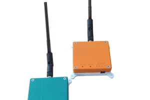
 ssla-couk