At last I have a LoRaWAN Micro:Bit device which meets my design goals and allows us to move on to investigate and develop uses and applications.Ten prototypes have now been built using PCBs from PCBWay, and are being deployed in useful tasks
The device is built as a small motherboard for the Micro:Bit.
The edge connector on the Micro:Bit is rather odd, and I do need more connections than the previous screw connections allowed. Besides the original use of power, serial data and reset, I now want to provide I/O connectors for sensors, and access the I2C bus on the Micro:Bit. Choosing which pins for the I/O connectors is important, and I made a mistake on my first prototype board using pins which provide LED Col drives, because these are sometimes used by the LED array.
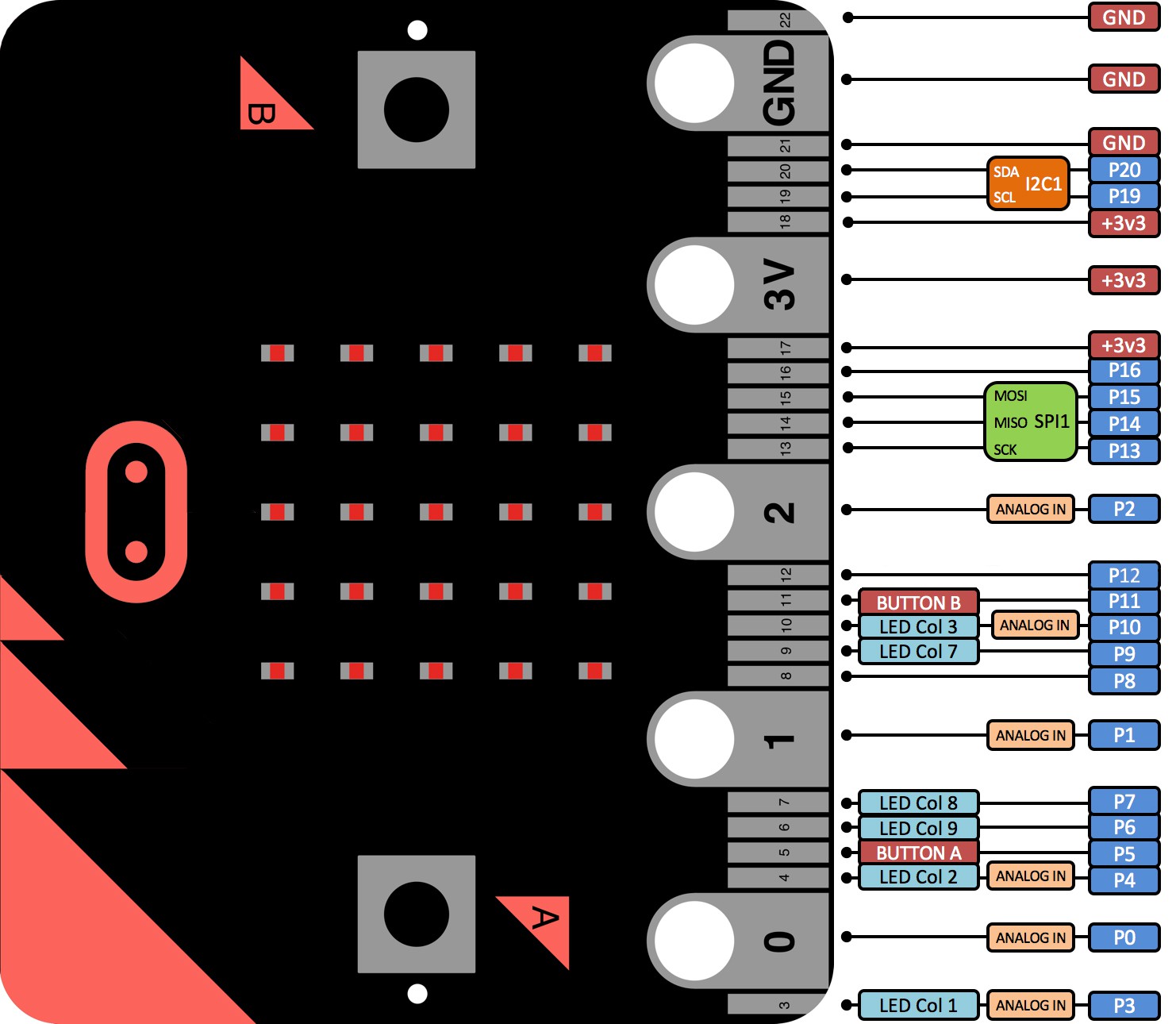
While described as a 22 wayedge connector, it is actually a 40 way double sided 1.27mm pitch edge connector. These are now available at reasonable cost on eBay in both horizontal and vertical mounting.
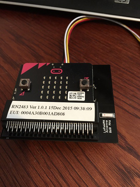
The motherboard carries the Microchip RN2483 LoRaWAN radio which still connects to the seraia port of the Micro;Bit. I added an on-board 868MHz antenna which seems to work just as well as the stub antenna I was using before. I used the 0868AT43A0020 ceramic antenna from Johanson Technology.
For power control I chose to add a separate Real Time Clock (RTC) chip, this gives low power while sleeping and fairly accurate timing. I choose the MCP7940N from Microchip as the RTC because it had an alarm function which I could use for the wakeup.Datasheet
The RTC connects to the I2C bus of the Micro:Bit. The I2C bus is also used on the Micro:Bit to interface the magnetometer and accelerometer, it is also brought out to a grove connector on the motherboard to allow connection of external I2C sensors.
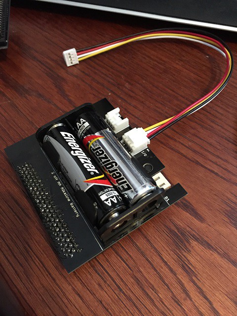
A battery pack with two AA size Alkaline Cells was added to the motherboard giving around 2000mAh at a nominal 3V output. The battery power is controlled with a MOSFET circuit which can power off the entire board electronics with the exception of providing backup to the RTC. The board is powered on by a push button, or when the RTC alarm is triggered.
Two grove sensor connector are mounted on the motherboard, One on the I2C bus, and one providing two general purpose Analog or Digital I/O
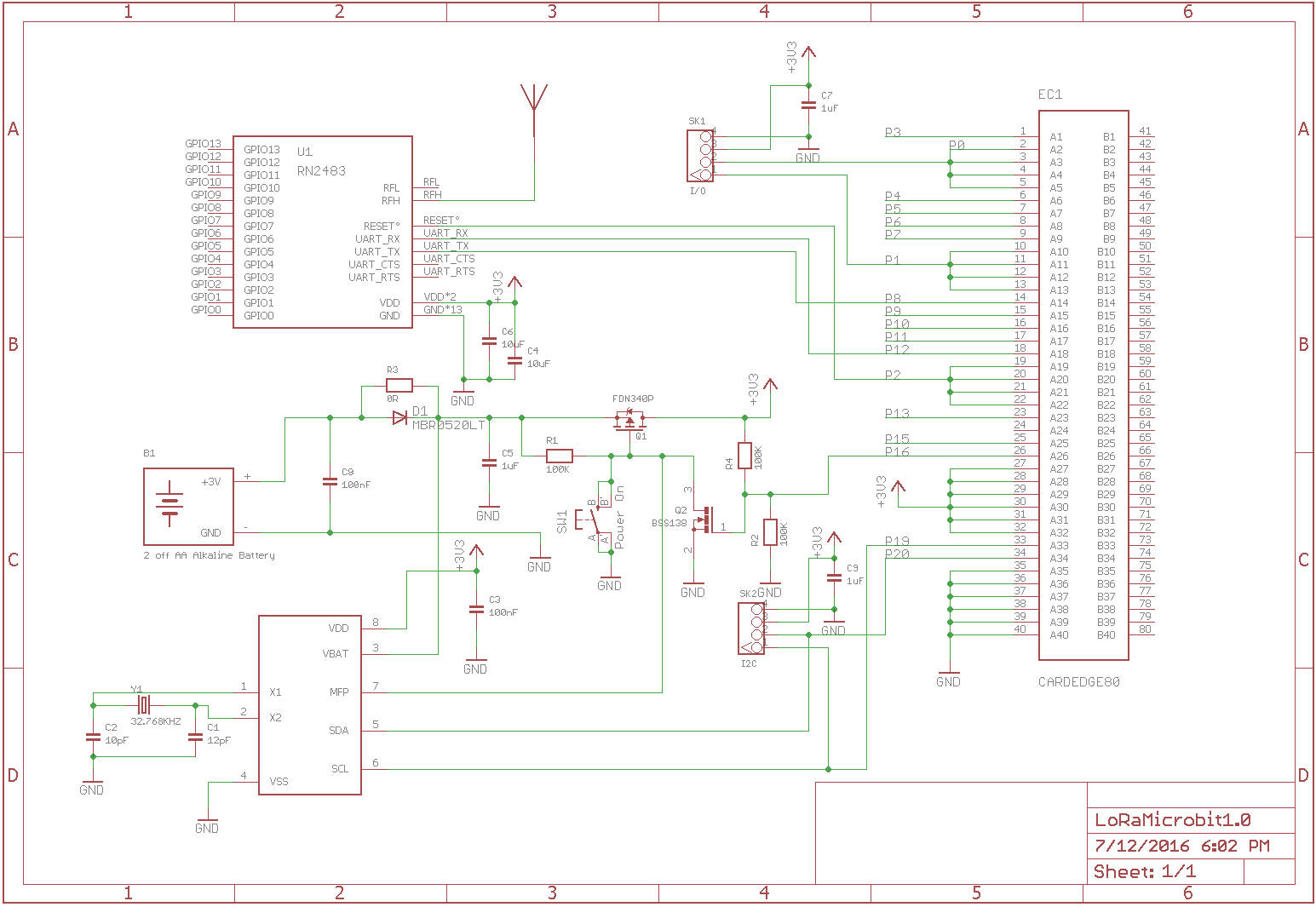
The PCB was designed in Eagle and the files are on my GitHub here: LoRaWAN_MicroBit
Micropython files have been updated to support the new pin allocations, and the inclusion of functions to control the RTC.
Discussions
Become a Hackaday.io Member
Create an account to leave a comment. Already have an account? Log In.