-
LoRaWAN for BBC Micro:Bit Motherboard
08/04/2016 at 10:23 • 0 commentsAt last I have a LoRaWAN Micro:Bit device which meets my design goals and allows us to move on to investigate and develop uses and applications.Ten prototypes have now been built using PCBs from PCBWay, and are being deployed in useful tasks
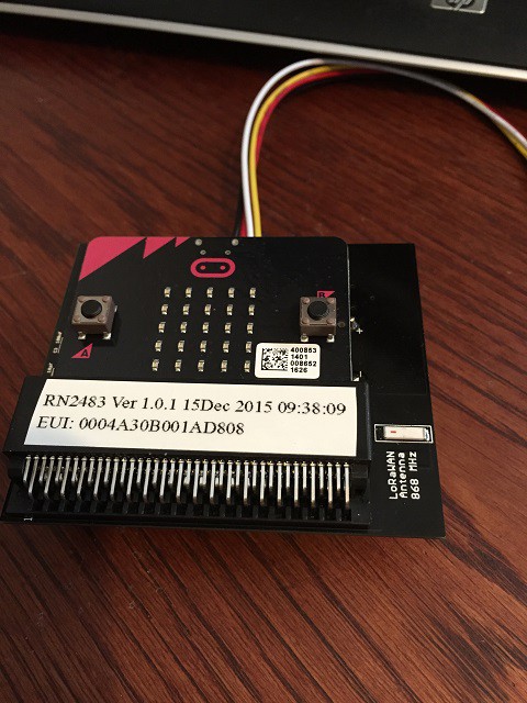
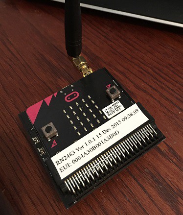
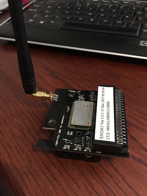
The device is built as a small motherboard for the Micro:Bit.
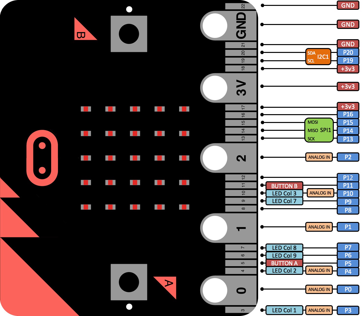
The edge connector on the Micro:Bit is rather odd, and I do need more connections than the previous screw connections allowed. Besides the original use of power, serial data and reset, I now want to provide I/O connectors for sensors, and access the I2C bus on the Micro:Bit. Choosing which pins for the I/O connectors is important, and I made a mistake on my first prototype board using pins which provide LED Col drives, because these are sometimes used by the LED array.
![]()
While described as a 22 wayedge connector, it is actually a 40 way double sided 1.27mm pitch edge connector. These are now available at reasonable cost on eBay in both horizontal and vertical mounting.
The motherboard carries the Microchip RN2483 LoRaWAN radio which still connects to the seraia port of the Micro;Bit. I added an on-board 868MHz antenna which seems to work just as well as the stub antenna I was using before. I used the 0868AT43A0020 ceramic antenna from Johanson Technology.
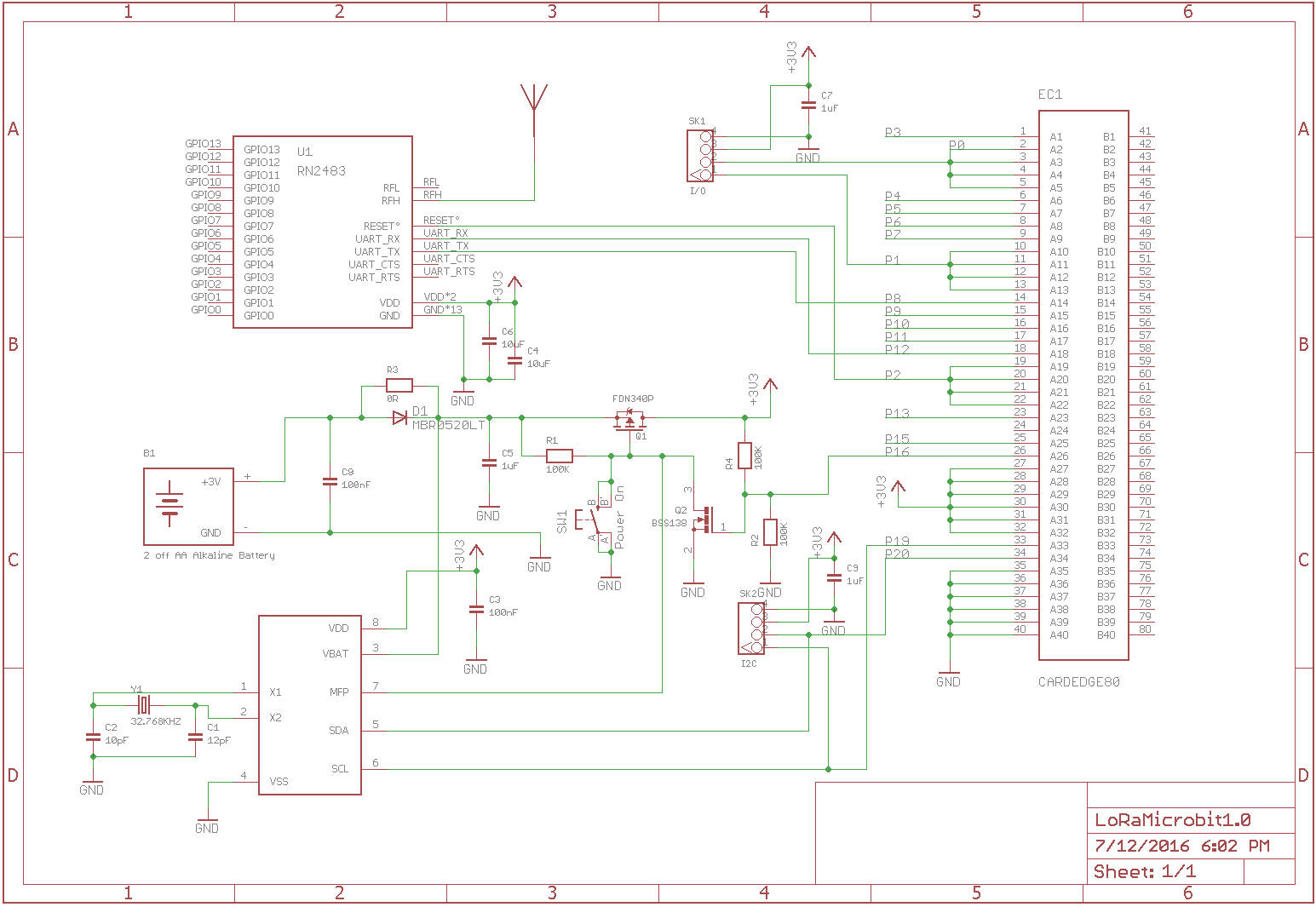
For power control I chose to add a separate Real Time Clock (RTC) chip, this gives low power while sleeping and fairly accurate timing. I choose the MCP7940N from Microchip as the RTC because it had an alarm function which I could use for the wakeup.Datasheet
The RTC connects to the I2C bus of the Micro:Bit. The I2C bus is also used on the Micro:Bit to interface the magnetometer and accelerometer, it is also brought out to a grove connector on the motherboard to allow connection of external I2C sensors.
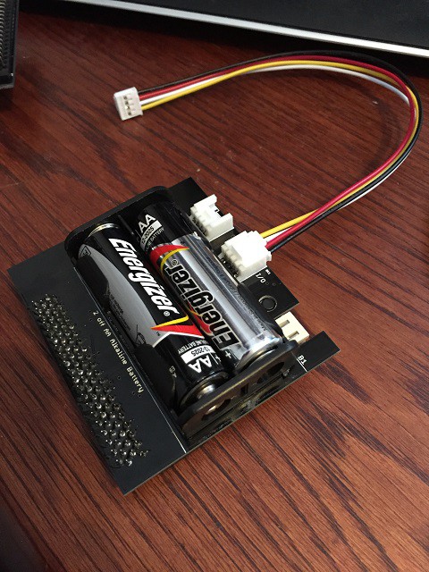
A battery pack with two AA size Alkaline Cells was added to the motherboard giving around 2000mAh at a nominal 3V output. The battery power is controlled with a MOSFET circuit which can power off the entire board electronics with the exception of providing backup to the RTC. The board is powered on by a push button, or when the RTC alarm is triggered.
Two grove sensor connector are mounted on the motherboard, One on the I2C bus, and one providing two general purpose Analog or Digital I/O
![]()
The PCB was designed in Eagle and the files are on my GitHub here: LoRaWAN_MicroBit
Micropython files have been updated to support the new pin allocations, and the inclusion of functions to control the RTC.
-
Been Doing Iot, but not sharing it, Sorry Folks!
07/31/2016 at 15:32 • 0 commentsOuch, I really didn't think it was so long since my last project log entry. I have been Just IoTing, Just not sharing with people what is happening. So to say sorry, and catch up:
First, the world has changed a bit. The BBC Micro:Bit is now available from UK distributors. bbc-microbit . Updates to MicroPython include a radio function, which is not Bluetooth, but uses the 2.4GHz radio in the NRF51822 for networking MicroPython Docs.. This might offer opportunities to network over a small area with 2.4GHz, then connect over LoRaWAN for longer distance. It does suggest however, that we will not be getting Bluetooth under MicroPython. I have not investigated opportunities to use C++, or Touch Develop.
My LoRaWAN network connection is to the Things Network, and that has had an update too Things Network Backend. A new staging back-end has been implemented with a more logical and open structure. Device nodes now use Over the Air Activation (OTAA) to get device addresses, so the network join process has changed. Also the Things network now provides no message storage, so applications need to collect messages from the Things Network using MQTT subscription or node.js, as they occur.
We held a LoRaWAN workshop at rLab(Reading Hackspace) on July 2nd 2015. This was really valuable to help us understand the changes in the Things Network, and better prepare end to end IoT solutions from device through to application. We updated the Multitech LoRaWAN Gateways, and sucessfully installed an additional LinkLabs Gateway based on the Raspberry Pi.
So to progress on the Micro:Bit LoRaWAN device node. Following the work to measure power consumption, I built a prototype PCB which contained not only the RN2483, but also an electronic power switch, and a Real Time Clock(RTC) Timer IC. This allowed the whole board except the RTC to be turned off between transmissions. Sleeping power consumption has dropped from 4mA to 1.1uA, meaning devices transmitting infrequently can have now have battery life of over a year. I made some mistakes and poor design choices on the prototype, so made a second run of the PCB with some fixes and improvements.
The pictures above are of the first prototype, I will do separate log for the new board
-
Reducing Power Consumption
06/16/2016 at 00:02 • 0 commentsPower consumption is clearly a major factor for IoT devices. The expectations of battery life for this device is for at least one month (750 hours+) of operation. The battery pack which came with the Micro:Bits is rated at 3V and 1000mAh. This means we have to get current consumption below 1 mA on average.
The consumers of the power are the Micro:Bit and the RN2483 radio. Initial measurements on the Micro:Bit are immediately not encouraging. Just sleeping, with no LED on has a current consumption of 1.75mA, and turning the LEDs on adds another 9mA. So even with the LED's off and doing nothing, we would drain the batteries in well undre our target of one month. So why is this ? The NRF51822 has great low power operating capability, but there is nothing in Micropython (Yet!) to take advantage of this. We could move to programming in C++ under MBed to get direct control of the NRF51822's power management, but that messes with our "Just do IoT" philosophy for using the basic toolchains provided. The circuit schematic of the Micro:Bit is not published, and it is also not clear how the second ARM M0 processor which does the USB interface is powered. It may be we can fix the NRF51822, but the USB chip while unused on battery power still sucks the juice. Maybe we bit the dirt on this project, or do we need a good hack!
Let's look at the radio anyways. The specification is a bit more clear here, with quoted values of 2.8mA at idle, 14.2mA on receive, 10uA on sleep, and 38mA on transmit. Some big numbers and a small one. However, the duty cycle of LoRaWAN is 1%, so it appears that the RN2483 could be power managed to meet our target of one month operation.
I did some measurements of current consumption of the whole Prototype system and on the RN2483 alone, while running the LoRaWAN Micropython program, which confirmed the figures above. The whole system took around 8.5mA at idle, which would maybe drop to around 8mA with the few LED's of the tick turned off. When transmitting the current jumped to around 50mA, but only for around 100mS. When receiving there is a smaller current jump to around 24mA as expected from the specification.
Looking at the RN2483 alone confirms the datasheet figures with 2.5mA at idle, and 40mA when transmitting. I sent the command to the RN2483 to enter deep sleep mode, and the current plummeted to around 2 uA, until the RN2483 awoke after the set sleep time.
So where from here ? I really hope the software developers for the Micro:Bit look to a power management strategy, but that will not help me short term. My decision is to add a circuit to turn power off to the device between transmission events.. This will be awoken by the deep sleep mode of the RN2483, or by an external Real Time Clock IC, which can power down the Micro:Bit between transmissions. This also gives the opportunity to make a PCB to hold the RN2483 and an edge connector for the Micro:Bit.
-
Project Log and To Do List
06/09/2016 at 13:21 • 0 comments09/06/16 Start project log here to show progress. Hardware proof of concept complete. Python program written to initialize radio and send data to TTN. Data received and identified from TTN api.
To Do:
Work on measuring and managing power consumption
Create a back end networ solution to process data and responses
Send meaningful data from switches, accelerometer or magnetometer
