 Daren Schwenke
This is the output you will get from the from the Yagi Calculator.
These measurements are only valid for a 3/4 in (19 mm) boom and 1/4 in (6.35 mm) elements.
VK5DJ's YAGI CALCULATOR
Yagi design frequency =725.00 MHz
Wavelength = 414 mm
Parasitic elements contacting a round section metal boom 19 mm across.
Folded dipole fully insulated from boom
Director/reflector diam = 6.35 mm
Radiator diam = 6.35 mm
REFLECTOR
212.4 mm long at boom position = 30 mm (IT = 96.5 mm)
RADIATOR
Single dipole 190.8 mm tip to tip, spaced 83 mm from reflector at boom posn 113 mm (IT = 86.0 mm)
Folded dipole 194.6 mm tip to tip, spaced 83 mm from reflector at boom posn 113 mm (IT = 88.0 mm)
DIRECTORS
| Dir (no) | Length (mm) | Spaced (mm) | Boom Position (mm) | Insert To (mm) | Gain (dBd) | Gain (dBi) |
| 1 | 184.4 | 31.0 | 143.7 | 82.5 | 4.8 | 6.9 |
| 2 | 182.0 | 74.4 | 218.1 | 81.5 | 6.5 | 8.6 |
| 3 | 179.8 | 88.9 | 307.0 | 80.5 | 7.8 | 9.9 |
| 4 | 177.7 | 103.4 | 410.4 | 79.5 | 8.9 | 11.0 |
| 5 | 175.8 | 115.8 | 526.2 | 78.5 | 9.8 | 11.9 |
| 6 | 174.1 | 124.1 | 650.3 | 77.5 | 10.5 | 12.7 |
| 7 | 172.4 | 130.3 | 780.5 | 76.5 | 11.2 | 13.3 |
| 8 | 170.9 | 136.5 | 917.0 | 76.0 | 11.7 | 13.9 |
| 9 | 169.5 | 142.7 | 1059.6 | 75.5 | 12.2 | 14.4 |
| 10 | 168.2 | 148.9 | 1208.5 | 74.5 | 12.7 | 14.9 |
COMMENTS
The abbreviation "IT" means "Insert To", it is the construction distance from the element tip to the edge of the boom for through boom mounting
Spacings measured centre to centre from previous element
Tolerance for element lengths is +/- 1 mm
Boom position is the mounting point for each element as measured from the rear of the boom and includes the 30 mm overhang. The total boom length is 1238 mm including two overhangs of 30 mm
The beam's estimated 3dB beamwidth is 37 deg
A half wave 4:1 balun uses 0.75 velocity factor RG-6 (foam PE) and is 155 mm long plus leads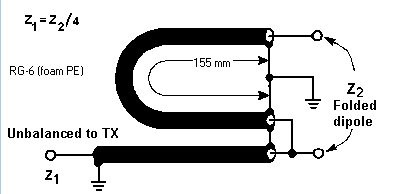
FOLDED DIPOLE CONSTRUCTION
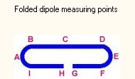
Measurements are taken from the inside of bends
Folded dipole length measured tip to tip = 195mm
Total rod length =422mm
Centre of rod=211mm
Distance BC=CD=80mm
Distance HI=GF=77mm
Distance HA=GE=104mm
Distance HB=GD=131mm
Distance HC=GC=211mm
Gap at HG=6mm
Bend diameter BI=DF=34mm
If the folded dipole is considered as a flat plane (see ARRL Antenna Handbook) then its resonant frequency is less than the flat plane algorithm's range of 10:1

 Elite Worm
 borysziel
 Jacob Nichols
 notme
notme