 adria.junyent-ferre
Below is a description of the project following the design process step by step.
High level design
I needed a clamp with a stable closed position that I could control from a microcontroller. The clamp didn't need to be too strong so I decided to keep things simple and use a clothes peg as the basis for the design. I initially thought I'd use an electromagnet from a big contactor to open the peg but I found out car lock actuators (see below) are strong enough and cheap (£3.95) and decided to use one.

The lock actuator has a "travel distance" of around 2 cm. It is meant to be fed short voltage pulses from the car battery (12V). The resistance of the coil is around 2 ohm, which means the motor will draw 6 A and produce 72 W of heat (!!!!) if fed this voltage continuously.
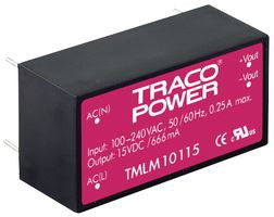
Because my application only needed the peg to open once or twice a minute, the actual average power I needed was much less than 72 W. I had a compact Tracto Power supply (TMLM10115 -see below) rated 12V at 0.83 A (£11) laying around and I thought I could combine it with a little power converter and use it in my application.
(Electro-) Mechanical design
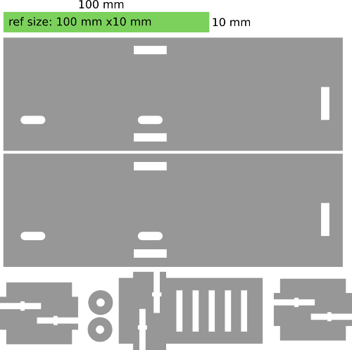
The first thing I needed to do was to figure out how much force I would need to open the peg and how long I would need the actuator to be applying force in order to open the clamp. I designed a laser-cut wooden frame to hold the actuator and the clothes peg in place. Rather than using a 3D modelling software, I drew the design in Inkscape straight-away as the geometry was simple enough.
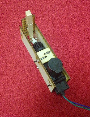
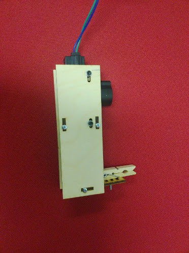
Once I got the actuator assembled, I used a signal generator and a power supply to apply voltage pulses. Unfortunately, my supply was unable to give more than 1 A, but I got a rough idea of the amount of time I needed to apply force from the actuator in order to be sure I'd open the peg (around 1 second).
The need for an energy buffer
For the design of the power converter, I thought it would be interesting to use capacitors to store the charge I needed to open the peg. A very rough estimation of the capacitance I needed was obtained by assuming I'd completely discharge the capacitors in around 1 second (therefore the time constant RxC needed to be 0.33 s). This gave a capacitance of 0.33 F. Such capacitance is hard to achieve using normal electrolytic capacitors but can be reached with ease using supercapacitors.
Supercapacitors are commonly used nowadays and can be sourced easily. Still, they have low voltage ratings and in many cases their effective series resistance is high as they are meant for low current applications (not my case!). After considering different series-parallel combinations, I found a 1 F supercapacitor rated for 2.7 V with a series resistance between 0.1 and 0.2 ohm (£1 per unit!). By combining 5 of those (£5!) I got an equivalent capacitance of 0.2 F with a rated voltage of 13.5 V and a series resistance of 1 ohm, which was ok for what I need.
A simple constant-current charging circuit
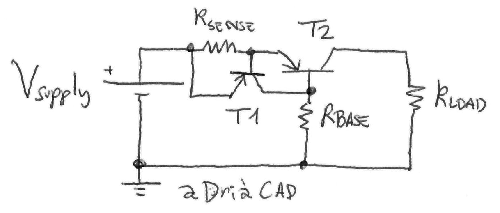
The next step was to decide how I would charge the supercapacitors. I was tempted to use a simple 15 ohm resistor between the 12V source and the supercapacitors, but I thought this would be too easy and I'd rather design something a bit more challenging. I decided to design a little non-linear resistor using BJTs. The circuit is very simple: a resistor in series with a power PNP BJT is used to sense the current, the voltage across the resistor is used to feed current to the base of a signal PNP BJT that will lower the voltage from emitter to base of the first BJT to lower the current (see below).
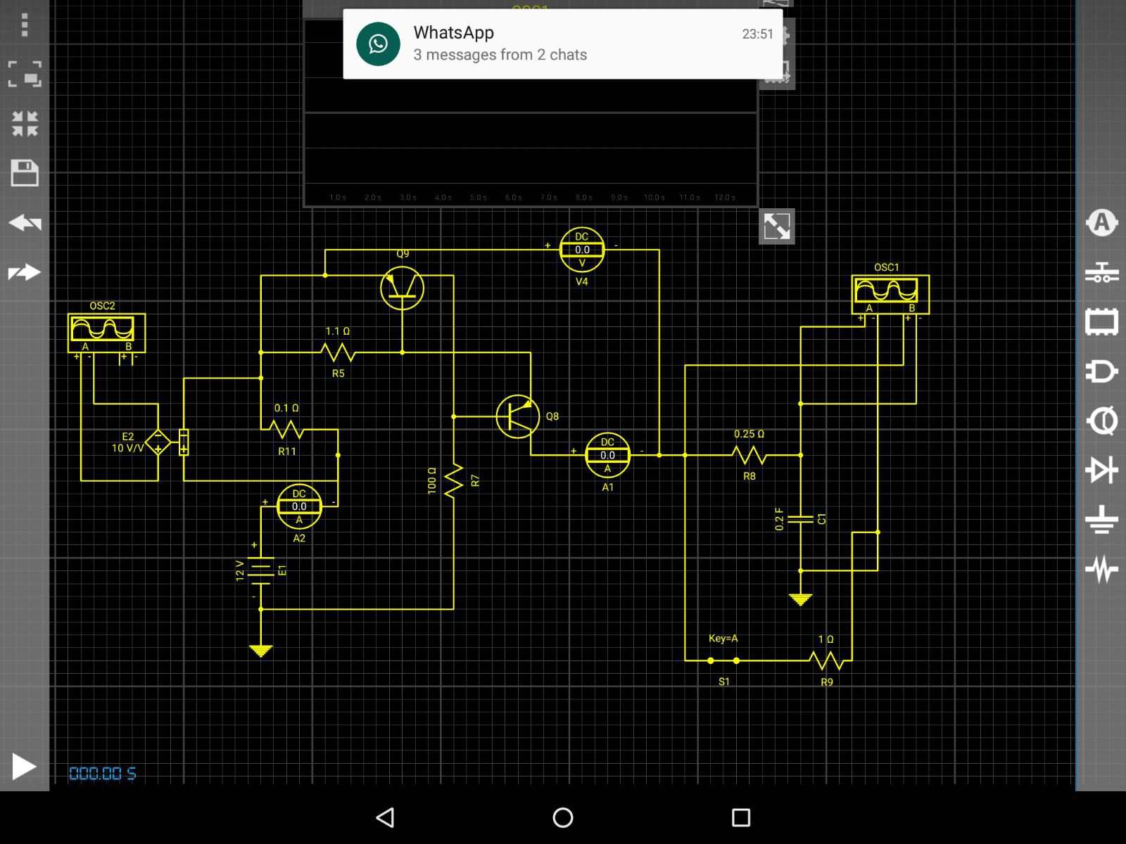
I tested the circuit in simulation using Droid Tesla simulator for Android, built the thing and surprisingly got very decent results at the first try. By the way, I like Droid Tesla because it is based on Spice and it is one of the few interactive circuit simulators for Android (if not the only) that has decent transistor models (Early effect, etc).
My greatest concern was the potential overheating of the devices. The power BJT operates in its linear region when limitting the current (around 8 W if the peg is kept open!) and the resistor I use to draw current from the base of the power BJT together take around 0.8 W in stand-by. The BJT should only operate for short periods of time which can be precisely timed by the microcontroller to avoid overheating. On the other hand, the resistor in base of the power BJT was implemented using three parallel resistors in order to spread the heat and keep them below their rated dissipation.
The motor driver
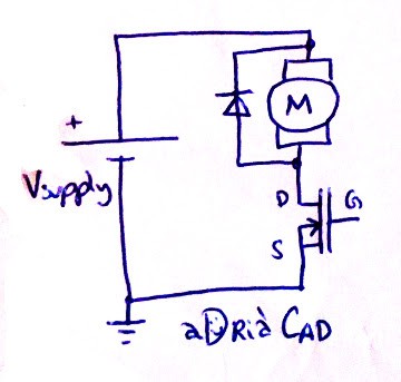
The next element in the circuit is the motor driver. As the spring of the clothes peg is strong enough to push the actuator back to its original position when no current is fed to the actuator and I didn't expect to recover any energy from the spring, I only needed a "one quadrant" motor driver (positive voltage and positive current only). The easiest form of that is a low-side switch configuration:
I chose to use a pair of IRF830 mosfets in parallel (each rated 4.5 A) because I had plenty of them. This mosfet is an overkill in terms of voltage rating (500V when 50V -or even less- would be sufficient in my application). This leads to a significant on-resistance 0.75 ohm (RDS for each is 1.5 ohm). This way, the series resistance of the circuit becomes around 3.75 ohm (1 ohm from the supercapacitors, 0.75 ohm from the mosfets and 2 ohm from the actuator). This limits the current of the actuator to around 3.2 A. I did a few tests and found out this gave enough force to open the clothes peg and I didn't bother finding a mosfet with better RDS.
The motor is an inductive load, therefore a sudden change of its current would lead to a very high voltage across it. This voltage would be seen from drain to source of the mosfet, potentially exceeding its voltage rating, which would eventually damage the mosfet. This is can be overcome by placing a diode in antiparallel with the motor. The diode allows the current of the inductor to decay slower, effectively limiting the voltage across the motor to the on-voltage of the diode. I used a random Schottky diode I had laying around and tested to make sure it was clamping the voltage correctly.
The next step was to design the driver for the mosfets. In PWM-driven applications this would require a bit of thinking as not only the choice of components but also the layout of the board has a significant effect on the stress of the mosfets and the efficiency of the converter. Here, these aspects were of lesser importance as the mosfet was only expected to switch on and off once in a second. I chose to use a low-side mosfet driver IR2121 I had available with a gate resistance of 46 ohm. I also used 47 nF + 10 nF ceramic and film capacitors for decoupling of the driver. I was unsure if these would be enough but I did a few tests to verify the switching transient was acceptable and I didn't see anything suspicious (no dips in the voltage, etc).
The IR2121 provides short-circuit protection if combined with a low-side current sense resistor but I didn't use it. I also put a pull-down resistor at the input of the driver to be able to power the circuit with the microcontroller's pins in high-impedance state without causing random triggering. I also built a little low-pass RC filter at the input of the driver to minimise the chances of high frequency noise triggering the driver.
Implementation, summary and some thoughts
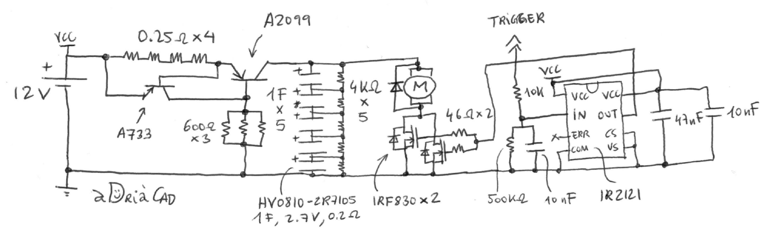
The complete schematic of the converter is shown below:
Rather than doing a proper PCB design, I built and tested the circuit step by step on a perfboard:
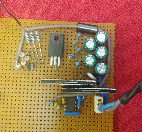
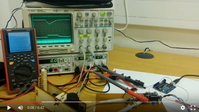
The layout is ugly and there's plenty of room for improvement. I've already done extensive testing and it seems to work fairly well but I guess time will tell how reliable it is. The easiest thing to improve is the section of the current limiter, where I have a relatively big loop. I also found a low-damped high frequency resonance between this circuit and the driver, which I sorted out the ad-hoc way with an ugly ferrite. The heat is generated mainly at the power BJT (where I have a heatsink not shown in the picture above) and the resistors of the base of the BJT. I made a simple Arduino sketch that would turn on the mosfet for one second every ten seconds and left it on for some half an hour to see if things would heat up too much and see if the circuit would work. I made a little video showing the circuit in action that can be watched here. The video shows how the supercapacitors charge and discharge (upper trace in the oscilloscope) and how the current drawn from the source looks like (lower trace in the oscilloscope):
Overall I'm pleased with the way the circuit works. Arguably my design choice is not the easiest nor the best because a simple relay could have been used to trigger the motor and a series resistor would have been enough to limit the current of the actuator and still be within the ratings of the supply (I believe 0.8 A are probably enough to open the peg). Still, the design process has been an enjoyable exercise and has plenty of room for future additions (for instance, I could do PWM and do current -or force- control).