Close
0%
0%

Pick and place machine

A pick and place machine optimized for small runs of different boards. Up/down looking cameras. Large number of feeders. Fast. Web interface

Similar projects worth following
A pick and place machine optimized for small runs of different boards.

-Up/down looking cameras for more accurate component placement.
-Large number of feeders to allow components for many boards to be left on the machine. Reels, loose tape and trays.
-Lagre pich ball screws for fast movement and low backlash.
-Large stepper motors for high acceleration and speed without risk of loosing steps.
-Epoxy/granite composite material in the base and some other parts for vibration damping.
-Linear guides (square) to make the machine rigid and precise.
-Web interface. The machine will have an ethernet connection and run a web server. The machine will be controlled trough the web interface.

Requirements

My goal is to build a pick and place machine which is practical to use for prototyping and small scale production. I believe there are several factors that are required to achieve this:

  • Reliability. The machine must just work, it can not require constant tweaking and maintenance.
  • Practical feeders. It needs to hold enough different components to allow all or most of the components required for several different boards to be left on the machine. It can not require all components to be on reels, it must accept loose tape as well as trays and tubes. It must also allow reels to be replaced individually, without needing to take other reels off the machine.
  • Practical usability. It must accept the Bill Of Materials from the users CAD software and have a quick way of associating each component with the correct feeder. The machine must be able to place a wide variety of components without operator intervention. This means multiple heads or an automatic tool changer.
  • Accuracy. It must be able to place small components, such as DFN or 0201. This means that the machine must have machine vision as well as a rigid structure and a means of precise motion.
  • Speed. Finishing each board quickly is essential even for prototypes and very small production runs as a pick and place machine can not realistically be left unattended. For larger runs a slow machine would be a bottle neck.
  • Size and noise. The machine must be of a size that can be placed on a table or work bench. It must be practical for two people to move. It must not require 3-phase power or an air compressor. The noise level must be low enough to not disturb neighbors if used in an office or apartment.
  • Cost. The machine must be designed for manufacturability. All the components used must be readily available in quantity at an acceptable prize. Manufacturing the machine can not be time consuming or depend on highly skilled people. (No lucky eBay-finds or parts forged from pure unobtainium in the heart of Mount Doom.)

  • It's alive!

    ZeptoBit01/20/2018 at 23:10 0 comments

    This took longer than expected... The macine finally placed it's first real board today! :) (A panel of 8 optically isolated USB-UART adapters). Many parts of the design has changed (some several times), an update is coming soon.

  • Video and updated documentation

    ZeptoBit08/20/2014 at 19:59 0 comments

    I have uploaded my video for the Hackaday Prize to YouTube and uploaded my design outline and my CAD-file for the mechanical design. Look at the left side for links.

    The design outline is the file to get if you want the most up to date and complete description if the project.

  • Updated System Design

    ZeptoBit08/19/2014 at 18:40 0 comments

  • Overview of the software

    ZeptoBit08/19/2014 at 18:34 0 comments

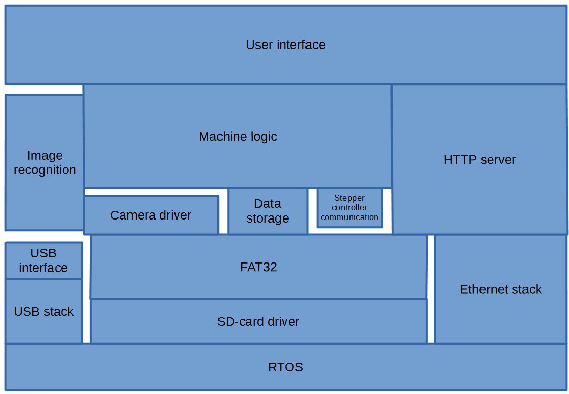
    Main MCU layered software diagram.

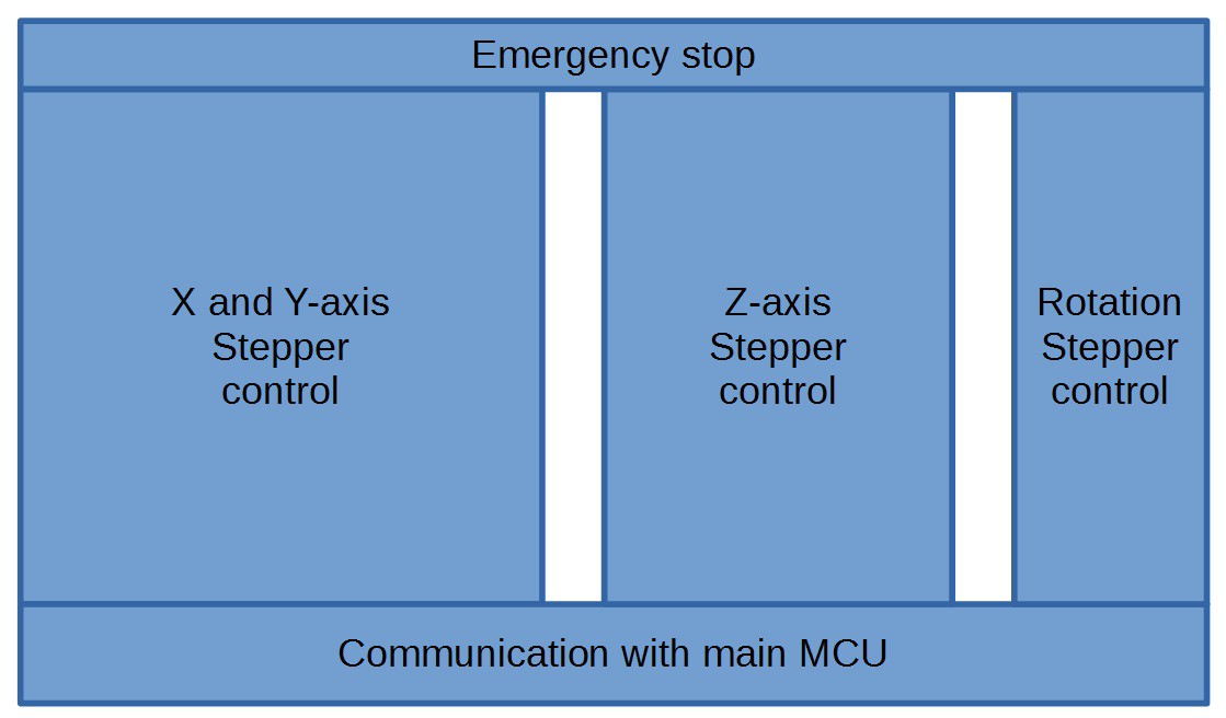
    Stepper controller MCU software diagram.

  • Update: Mechanical parts

    ZeptoBit07/31/2014 at 16:19 0 comments

    I'v been working on the base plate and some other mechanical parts of the machine. The base plate has a large number of M5 threaded holes to attach the feeders and fixtures for holding the board beeing populated. I'v finished drilling the holes, but I'v not finished tapping all yet. The Y-axis linear rail, ball screw bearings and motor mount also attaches to the base plate.

    I was a bit worried about the fit of the ball screws into the bearings, but there was no problems. I left the bearings in a warm place and put the screws in the freezer. With  50 or 60C difference in temperature the bearings could be pushed on, no hammering required.

  • Update: Electronics

    ZeptoBit07/31/2014 at 15:38 0 comments

    I finished hooking up all the electronics except the cameras and the limit switches about 3 weeks ago. Here's some pictures.

  • Progress update

    ZeptoBit06/24/2014 at 08:45 0 comments

    Stepper driver
    I have finished the firmware for the stepper controller. This is a separate microcontroller which receives commands from the main microcontroller over UART. Each command consist of which axis to move, which direction and how many microsteps to move. The stepper controller calculates ramp up timing etc. Step generation is the only part of the firmware where timing is critical, so keeping it separate simplifies the rest of the firmware.

    Change of main MCU
    I have switched to a LPC1768 based Arch-Pro board for the main microcontroller. Ethernet is now working reliably. Since this board doesn't have a socket for SD-cards I made a small board with a micro SD-card socket.

    Other..
    I have made a box with individual power switches for each power supply and an emergency stop switch. I'v (somewhat) sound proofed a box for the vacuum pump. 

    I'm still waiting for the ball screws to arrive. I would like to have the ball screws before I start machining the parts so that I can verify that the dimensions I have based my plans on are correct. I'm also waiting for some ER20 collets for the mill. Once I have these I can do all the machining in a day or two.

  • Received more parts

    ZeptoBit06/19/2014 at 17:50 0 comments

    I have received most of the parts I need for the project, except the ball screws and bearings.

  • Hardware progress

    ZeptoBit06/15/2014 at 19:56 0 comments

    I have received the vacuum pump. I have tested it and there was no problem picking up components, so it looks like it's large enough. It's a bit noisy, but not too bad. I will mount it in a box to dampen the sound a bit. The power for the pump will be controlled by PWM to keep it running as slowly as possible to make it last longer and to reduce noise.

    I cut a aluminium plate to size and drilled holes to mount all the power supplies, stepper drivers and all the boards. I'm mounting everything like this to have it easily accessible for probing and modifications. In the finished version all of this will most likely go into the base of the machine. 

    I'v cut out the base of the machine from a 12mm aluminium plate. (No picture yet.) Next I will drill and tap all the holes needed to mount feeders, the Y-axis linear rain, stepper mount, bearing blocks and the PCB holding fixtures. I will cast an epoxy-granite composite base under the plate, but I have not decided if I'm going to do it before assembling the machine or as an improvement later.

  • Software progress

    ZeptoBit06/15/2014 at 08:15 0 comments

    I'v been working on the software and have made some progress. I have decided to run the software on two micrcontrollers instead of one, that way I can separate the timing critical step generation for the stepper drivers from everything else. The MCU controlling the steppers is a Cortex M0+, for prototyping I'm using a FRDM-KL25Z board. The stepper controller is about 50% finished. My Salea logic analyzer turned out to be very useful for this, I use it to check the timing of the signals from the MCU to the stepper drivers.

    Support for Ethernet on the K64F by the mbed libraries has turned out to be unfinished/buggy. Because of this I'm going with an LPC1768 MCU on a Seed Studio Arch-Pro board. This MCU has some disadvantages, such as lower frequency, no FPU and less RAM, but I think the advantage of stable libraries outweighs this. For this project only the smaller RAM matters as it can't hold a complete picture from the camera in memory at once. My algorithm for finding the location of components in the images doesn't require the whole image to be in memory so this is not critical but more memory would be nice. I may switch back to the K64F if and when mbed support improves.

View all 15 project logs

Enjoy this project?

Share

Discussions

jjavor wrote 09/15/2021 at 16:14 point

This is a fantastically useful project! Do you have an estimate of at least an order of magnitude cost of parts?

  Are you sure? yes | no

LukeGary_462 wrote 07/12/2014 at 17:34 point
How will you implement the vision system?

  Are you sure? yes | no

ZeptoBit wrote 07/31/2014 at 16:06 point
I have not finished implementing the visions system, but it will use two OV7660 cameras with a FIFO memory. There is a library for the camera module, so I don't expect any problems geting the images from the cameras, which is good because I expect the vision system to be tricky enough as it is..

I'm doing a few things to simply the vision system. First I'm not using any kind of generic image/pattern recognition, it's specific for the most common component shapes.

Second I will have piece of black, non-reflecting material around the vacuum pickup nozzle and the component will be illuminated. This gives a high contrast so that the component appares white on a black background.

Basically the algorith looks at vertical and a horizontal lines from the image. It checks the value of each pixel until the value increase, indicating the edge of the components. This is repeated from rigth to left, with the difference in the number of pixels on each side being a measure of the misalignment. This is repeated on the vertical lines. By repeating on several lines roation of the component can also be detected and noise can be reduced.

I think this will work for rectangular, non-leaded components. For components with leads I plan on reading more lines and either average away the leads or detect them.

Sorry about the slow reply!

  Are you sure? yes | no

ZeptoBit wrote 06/15/2014 at 07:32 point
Thank you for your comment.

  Are you sure? yes | no

Adam Fabio wrote 06/12/2014 at 02:32 point
Thanks for entering your pick and place machine in The Hackaday Prize! I've seen a lot of projects to build these machines come and go, but rarely do they end up in production - I'm thinking you'll be one of the lucky ones, because you've got a good design so far. Don't forget to keep documenting!

  Are you sure? yes | no

Similar Projects

Does this project spark your interest?

Become a member to follow this project and never miss any updates