 Mihir Garimella
Although our hackathon project was a great proof of concept, we needed to make several improvements to get closer to a final product. One improvement that we thought of was a new enclosure: our hackathon prototype was literally made out of cardboard and glue, which worked well in a time-limited environment but wasn't very robust. For example, the camera mount wasn't attached to the actual body of the Google Cardboard, so it needed to be positioned properly before each use to ensure accurate eye tracking. Also, a new enclosure would be the starting point for a new prototype, as a new enclosure would afford us significantly more flexibility in design (e.g., we could replace the external computer that ran the eye tracking code offline with an onboard embedded platform that would perform the vision tasks in real-time).
We thought about what our enclosure should look like and we ended up splitting it into three discrete parts: the top, which would contain the LED's to show the user a visual pattern; the middle, which would hold the two cameras for eye tracking; and the bottom, which would hold the Raspberry Pi and other circuitry. Next, we modeled each part in Google Sketchup, with a particular focus on making the parts easily printable with minimal support material.
Here's the top:
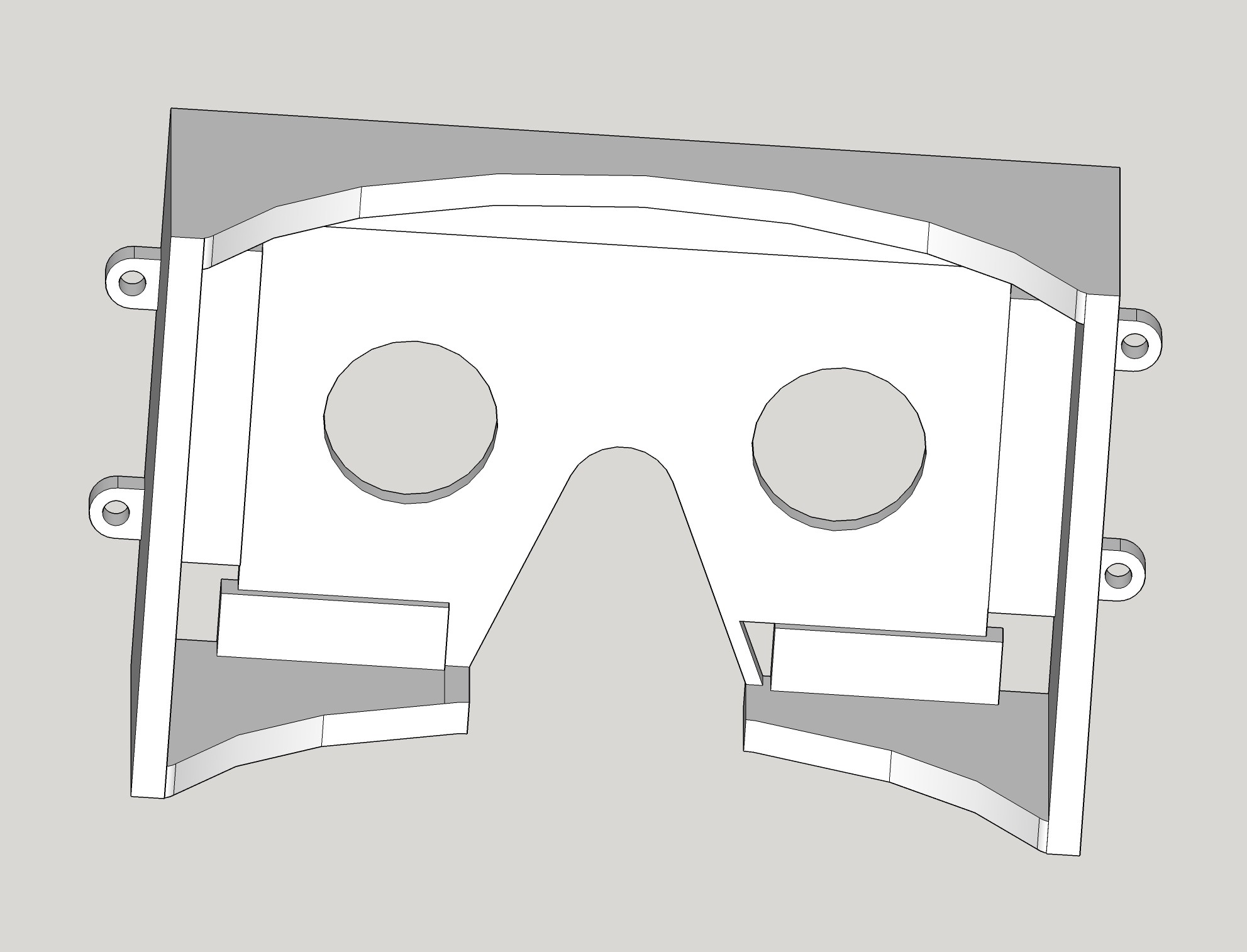
We used the original Google Cardboard drawings to model the forehead and nose cutouts and the eye holes. Next, we added raised platforms around the edges for LED strips, which we thought would be much cleaner than individual LED's. We added small holes next to each LED strip (except the one on the bottom left, where the strip starts) to contain the wire used to chain the strips together. Also, we added four M3 screw holes around the sides to attach the top piece to the middle.
Here's the middle:
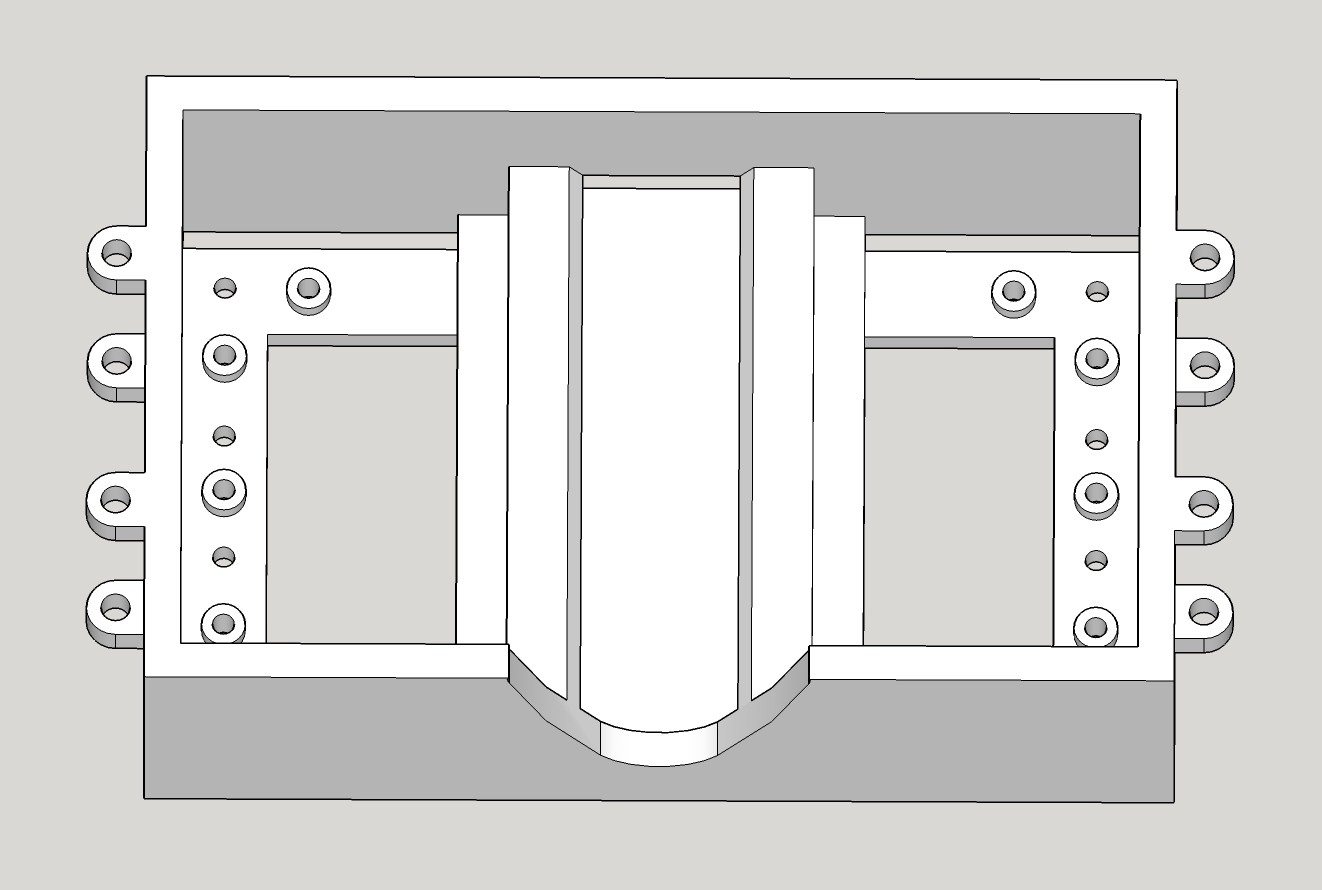
Again, we used the original Cardboard drawing to model the nose cutout on the bottom. We added a slot in the middle for the battery and several M2 screw holes on each side for the PS3Eye cameras (positioned based on measurements on the camera circuit boards carefully taken by hand). We cut out the material behind the cameras to provide room for the cables to pass through. We also added M3 screw holes around the sides on both the top and bottom, to attach the middle to the other parts.
Here's the bottom:
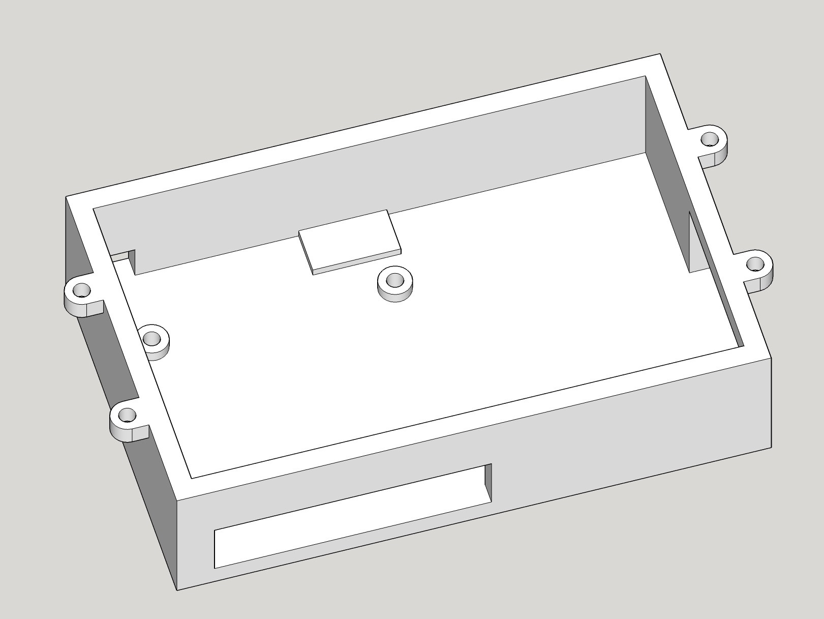
We added M3 standoffs to attach the Raspberry Pi (two aren't pictured). We also added cutouts for the Raspberry Pi's ports (minus one set of USB ports on the top to which we were directly going to attach the cameras). In addition, we added a small raised platform on the top for a voltage regulator, with a cutout in the top left corner of the enclosure for the battery cable to pass through. Finally, we added M3 screw holes around the sides to attach this module to the middle.
(You can access all of these CAD models from the Dropbox link in the sidebar.)
Discussions
Become a Hackaday.io Member
Create an account to leave a comment. Already have an account? Log In.