(Also published here.)
Getting HDMI TX up and running was pretty straightforward: there was already a very small example design with the Terasic board. Doing the same for HDMI RX is proving to be more complicated.
There is no simple small design on the web that can be used. There are two projects on GitHub that use an SiI9233 or an SiI9135 (which is pretty similar), but so far, even getting my PC to recognize the Color3 board as potential valid sink (by reading the EDID over the DDC wires) hasn't been successful.
I always knew that the real solution could be found in dumping the control I2C transactions of the SiI9233. But for that, I'd have to solder some probe wires on the CSCL and CSDA pins of the TQFP144 packages. These pins are spaced 0.5mm2 apart. Even with reading glasses and magnifier, my eyes are simply not good enough to make that happen.
I Needed A Microscope!
The real pros are using microscopes from Vision Engineering. New, these things cost a small fortune, but second hand, you could find old ones starting at $400.
But for soldering a few wires, even that is a little bit over the top, so I settled for a Bausch and Lomb StereoZoom 4 for $95, including stand.
As luck would have it, the eBay seller was located in Santa Clara, so last Thursday we exchanged money for goods on the parking lot of Fry's in Sunnyvale.
This is the result:
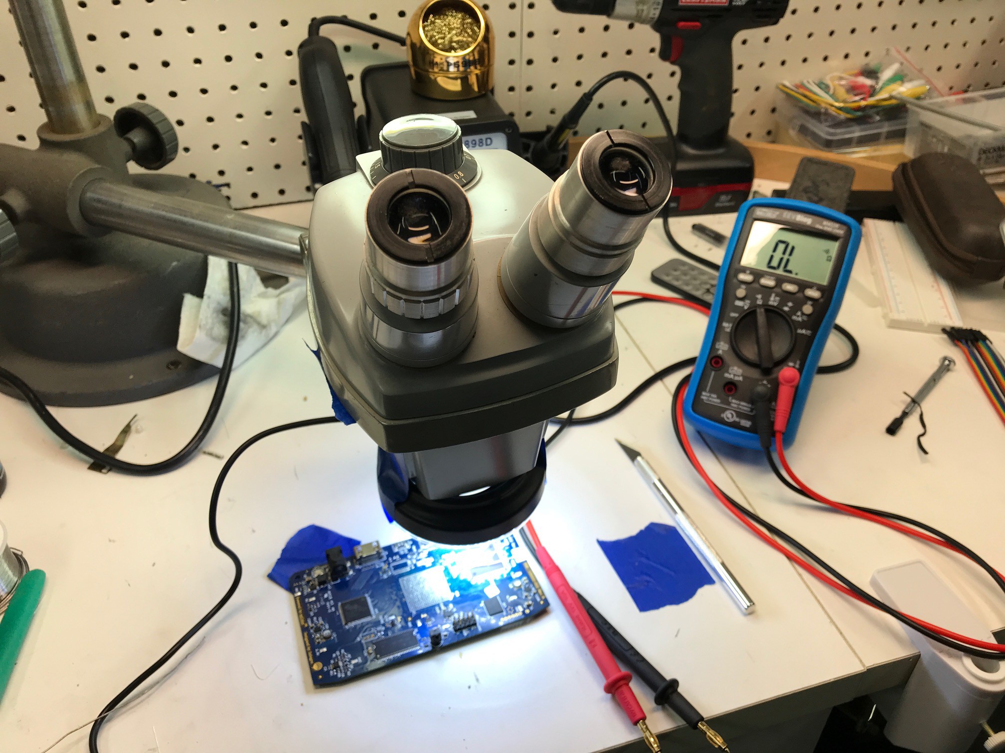
The magnification is not great: only 7x to 30x, but when soldering, I only use the lowest magnification setting anyway. I bought an LED illumination ring separately. It doesn't fit, but that's easily fixed with some painter's tape.
And with that, I could start to practice my TQFP144 soldering skills.
First on my broken board:
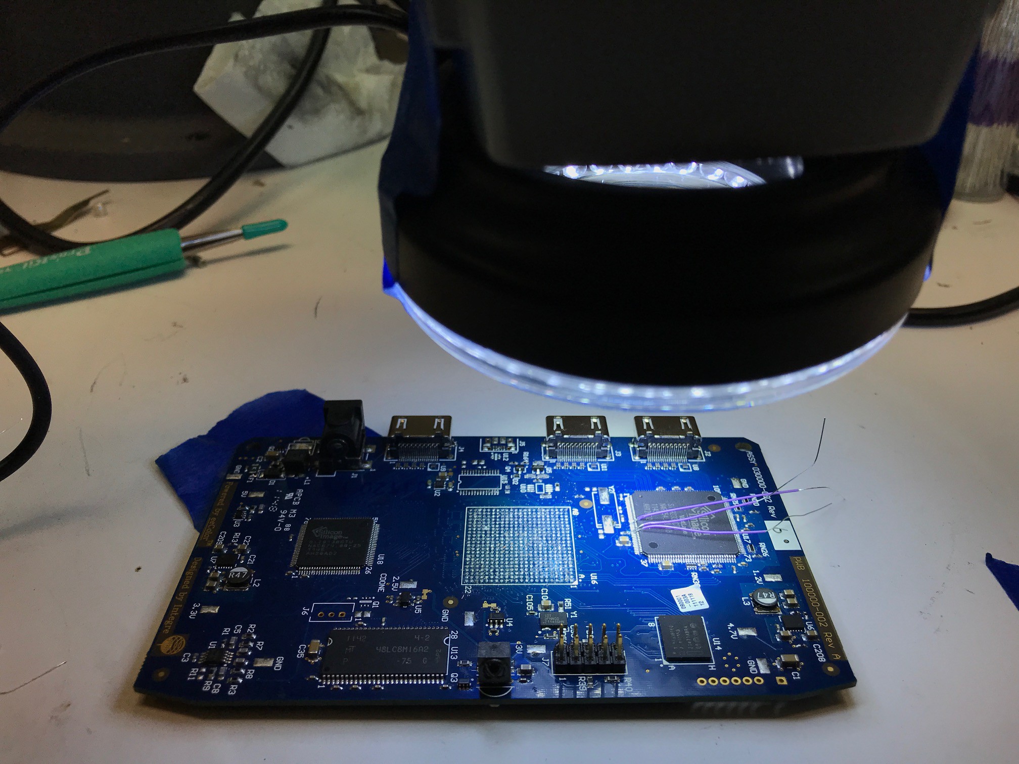
Soldering those little wires was surprisingly easy. Initially, I used tweezers to hold the ultra-fine wire-wrap wires, but holding it my fingers directly worked better in the end.
After practice, it was time for the real thing:
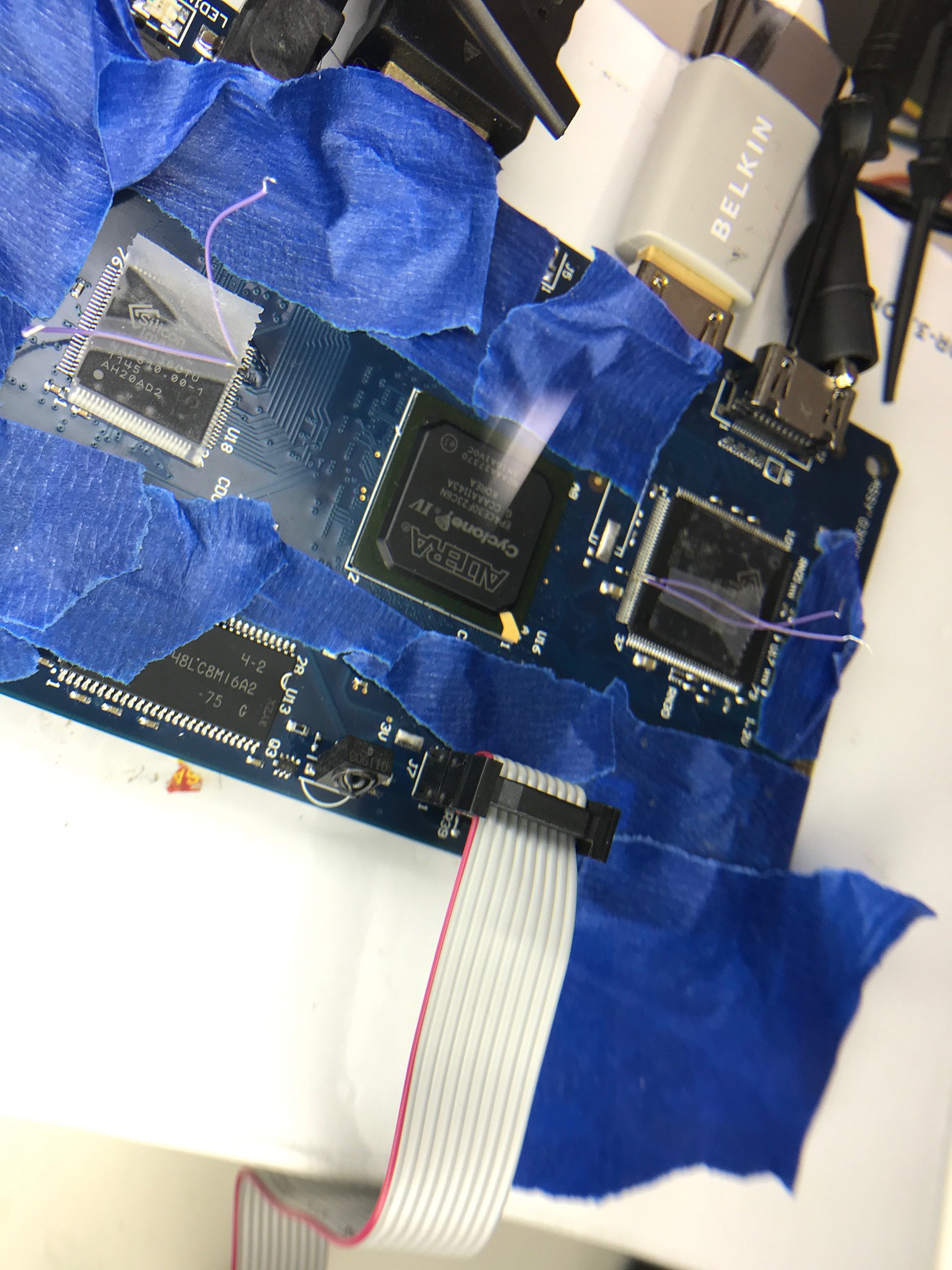
Notice the two sets of wires: one on the SiI9233 and one on the SiI9136, because I might as well record the transactions on that one too.
With a Saleae Logic probe and the Logic software, the I2C transactions came out beautifully!
The results can be found here:
https://github.com/tomverbeure/color3/tree/master/reveng/recordings
You can also find the `process.rb` script there. It tries to decode the registers, based on the definitions in the linux-meson and HDMI-4-OUT projects on GitHub.
While understanding what the transactions actually do will probably be useful at some point in the future, I think that the easiest to proceed is to simply replay those I2C transactions on my design and see what happens.
Discussions
Become a Hackaday.io Member
Create an account to leave a comment. Already have an account? Log In.