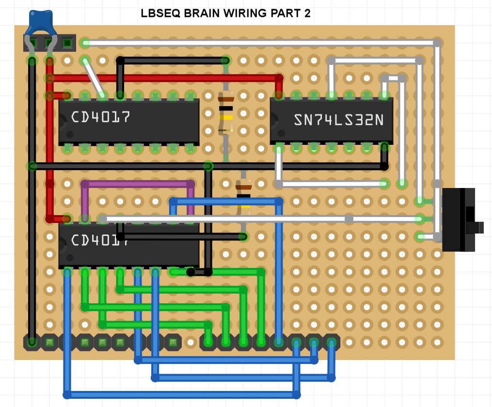
I've got lots of small prototype PCB's so it makes sense to break this project up into several modules. This is my first attempt at designing the central unit aka brain of the sequencer. This module contains all the IC's and will connect to the output module(s) with jackports and LEDs. I've already built a simple LFO module that will provide the clock signal. This will be a stripped-down version with minimal functionality for test and demonstration purposes.
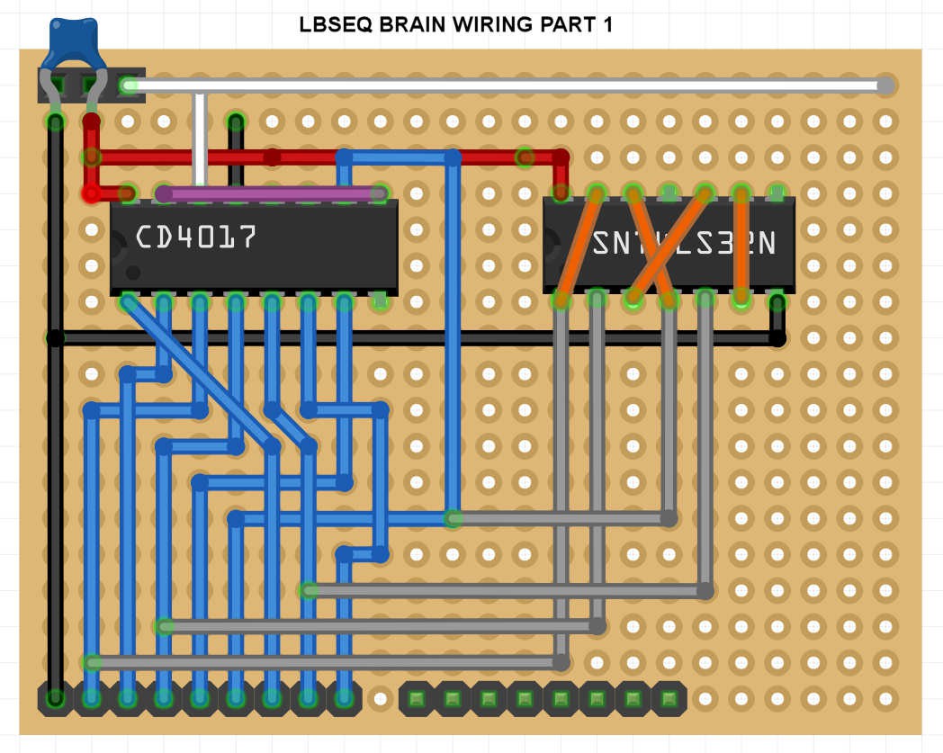
I've started building the circuit. I've soldered the chip sockets into place and about 80% of the wiring is done. I'm waiting for the 100K resistors to arrive in the mail before I will proceed with the rest of the work.
UPDATE: I've updated the wiring diagrams for clarity. Haven't been able to source a suitable 4 position switch to select the clock signal for the second row so I have just added 4 female DuPont headers and soldered a male cable to the clock input of the second decade counter.
The brain is ready! I've soldered all the wires and it's messy spaghetti. Lesson learned: don't go with the very first layout you can think of; make one or two revisions before you start the build.
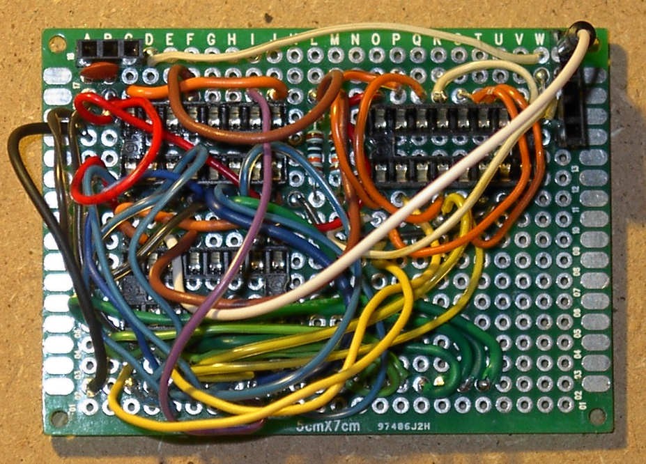
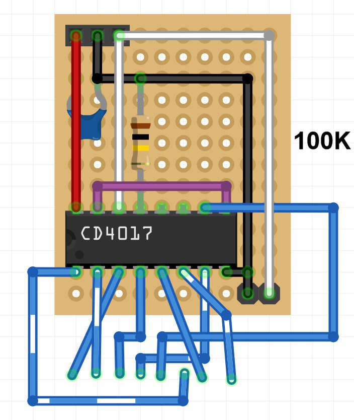
A bit too complicated for comfort! Wiring this was quite a challenge. And it won't be easy to fix or repair if something goes wrong. So I decided to start off by building a simpler brain module that will control only one row of steps. The clock divider and second row will be moved to separate boards. And i'll probably use a pair of dual J-K flip-flop ICs for the clock frequency divider.
I present the Mini Brain, revision C:
Discussions
Become a Hackaday.io Member
Create an account to leave a comment. Already have an account? Log In.