Close
0%
0%

Goliath - A Gas Powered Quadcopter

A BIG Gas Powered Quadcopter

Public Chat
Similar projects worth following
Goliath is an open source prototype vehicle for developing gas-powered quadcopters.

Overview

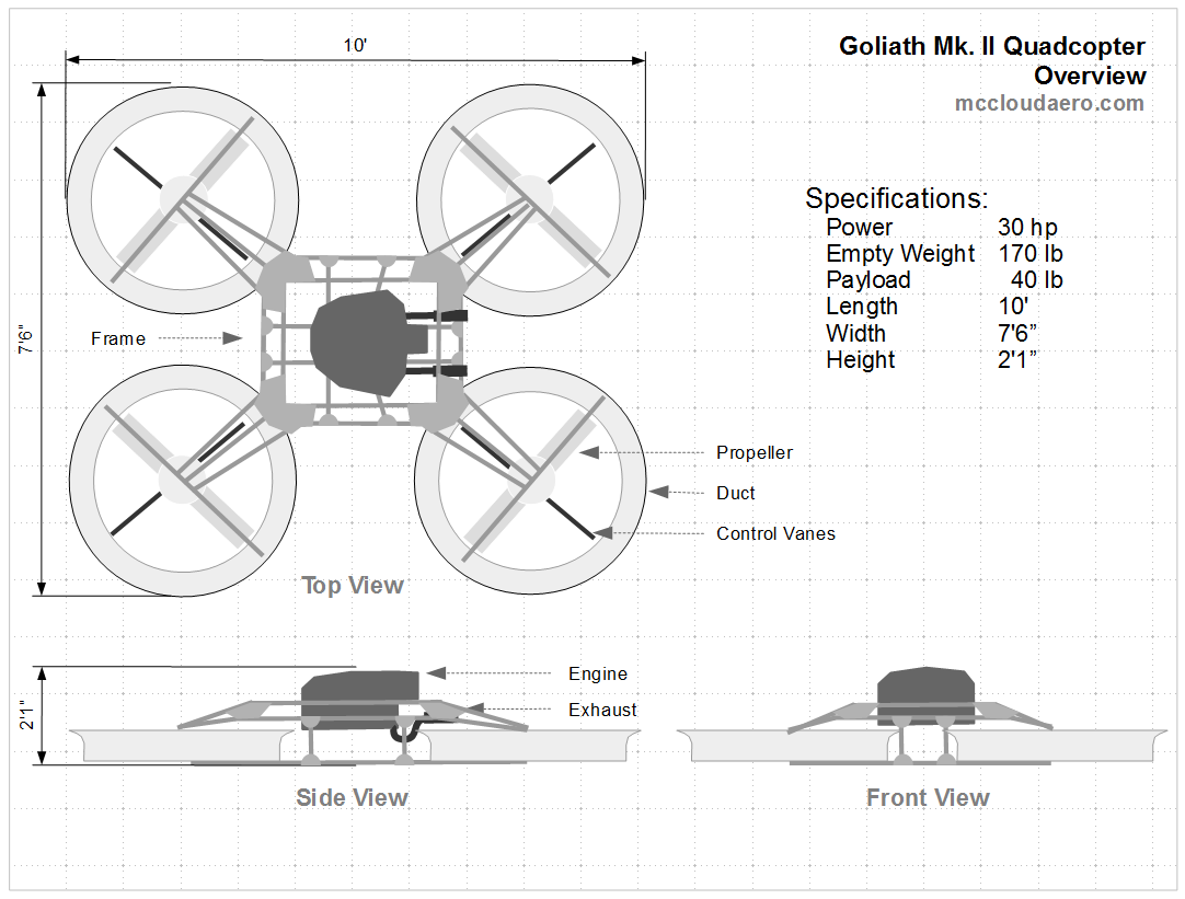
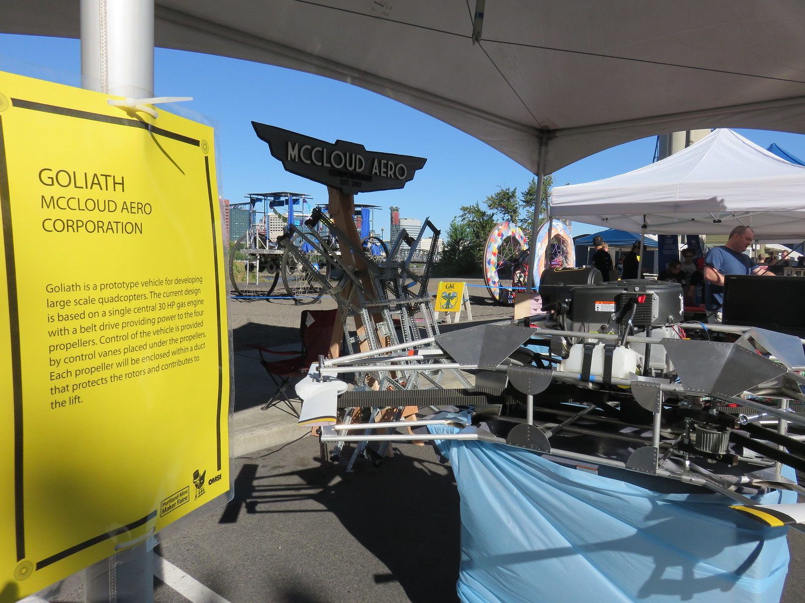
Goliath is a prototype vehicle for developing large scale quadcopters. The current design is based on a single central gas engine with a belt drive providing power to the four propellers. Control of the vehicle is provided by control vanes placed under the propellers. Each propeller will be enclosed within a duct that protects the rotors and contributes to the lift. Goliath itself will be open source with the creative commons license, and whenever possible open source components are used.

The Mk I vehicle was focused on developing the drive train. The Mk II vehicle was built with lighter weight aluminum frame. Even when completed Goliath is intended as a starting point for future vehicles.

Flight control will be performed using the Pixhawk controller running the PX4 flight stack.

Related Projects

#Inexpensive Composite Propellers/Rotors

#Drone Test Stand

#Measuring Engine RPM with the Pixhawk

#EVPR: Electric Variable Pitch Rotor

Current Status: HOVERING!

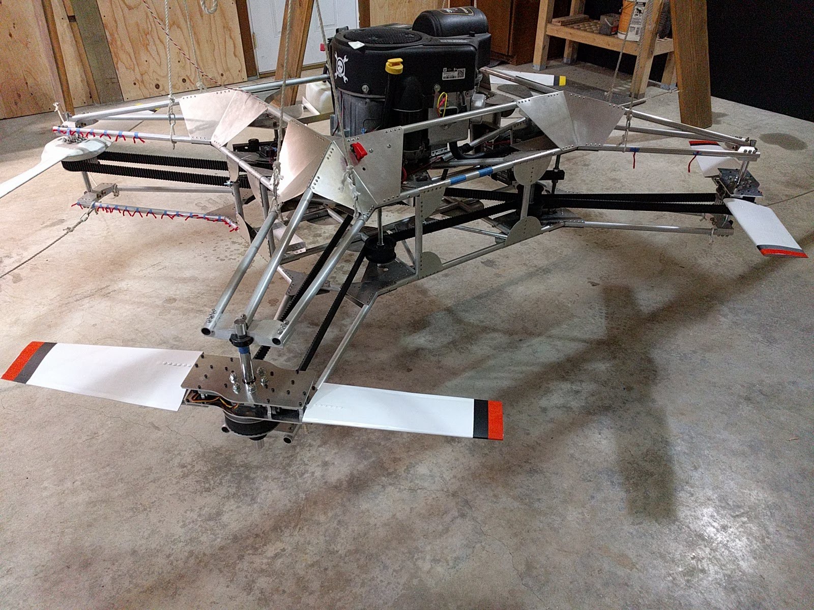
The Mk II vehicle has been assembled and hovered for the first time in September 2016.


Details

Structure

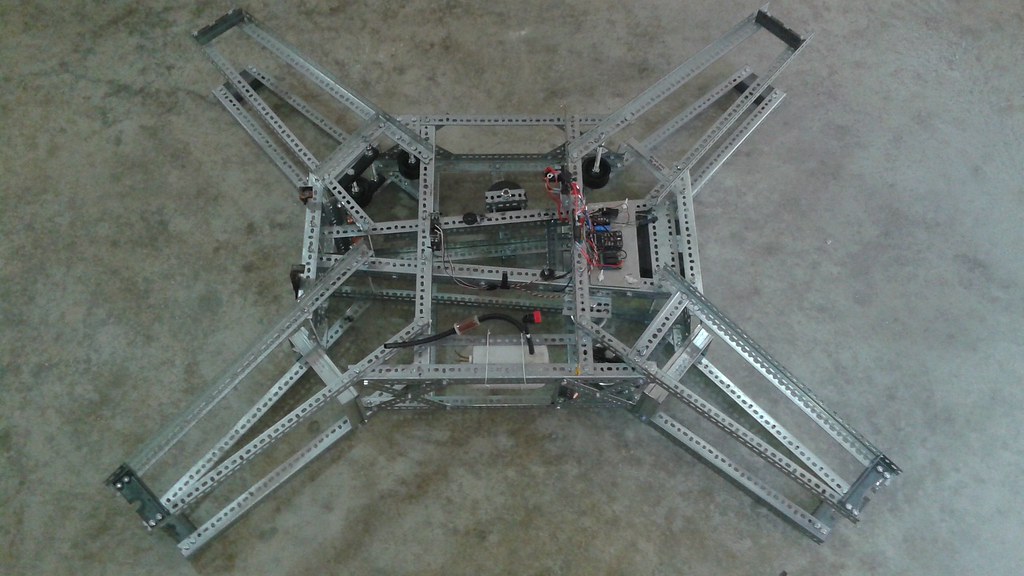
The initial Mk I frame was constructed using slotted galvanized angle, also known as Dexion, bolted together. While this is heavier than a steel tube or composite frame, the dexion is quickly assembled and can easily be reconfigured. This allowed for multiple iterations of the drive system to be tested with a minimum of time and cost.


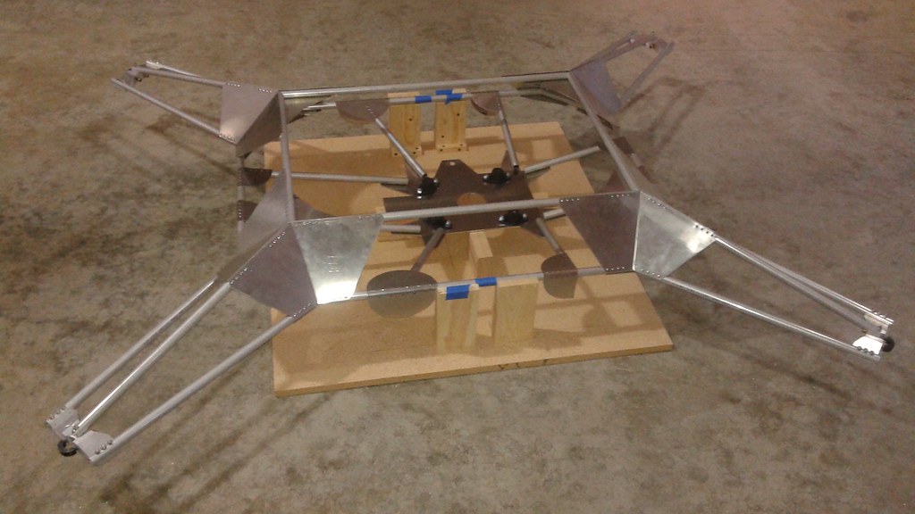
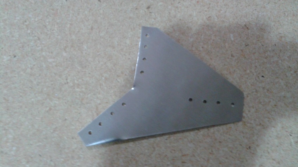
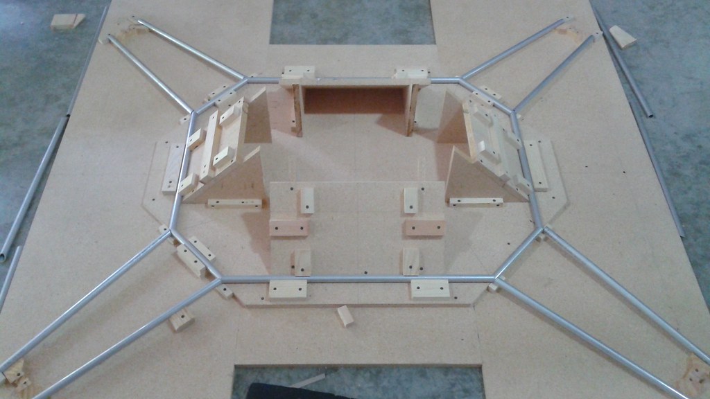
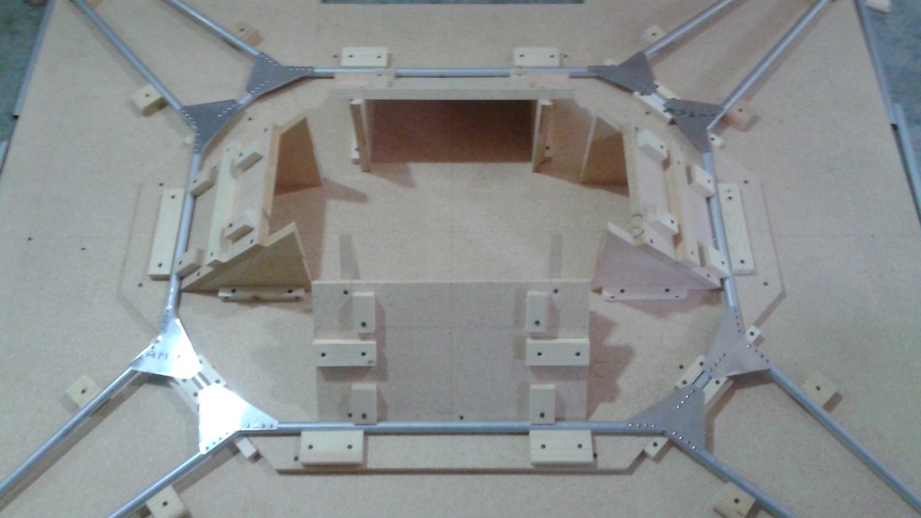
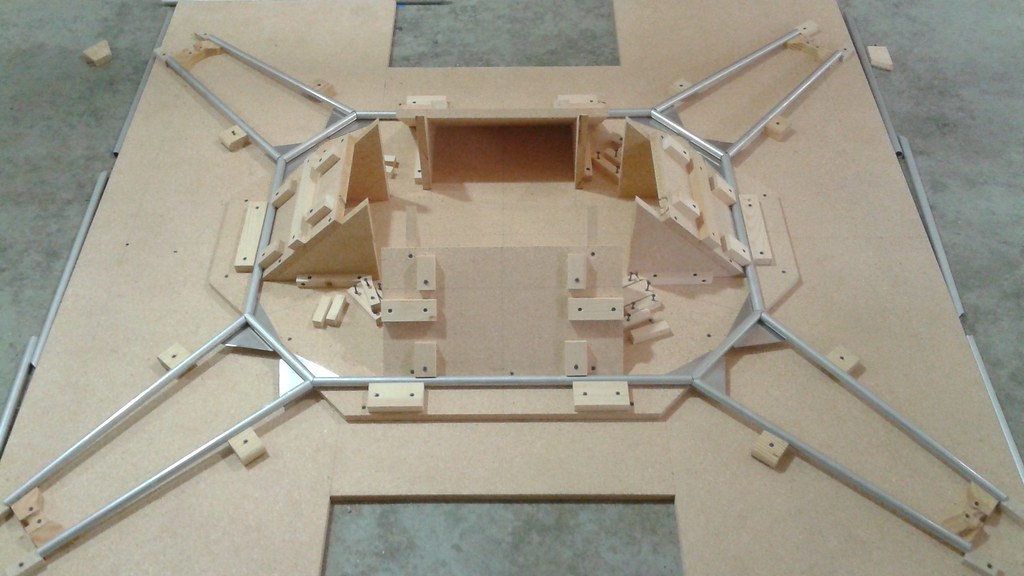
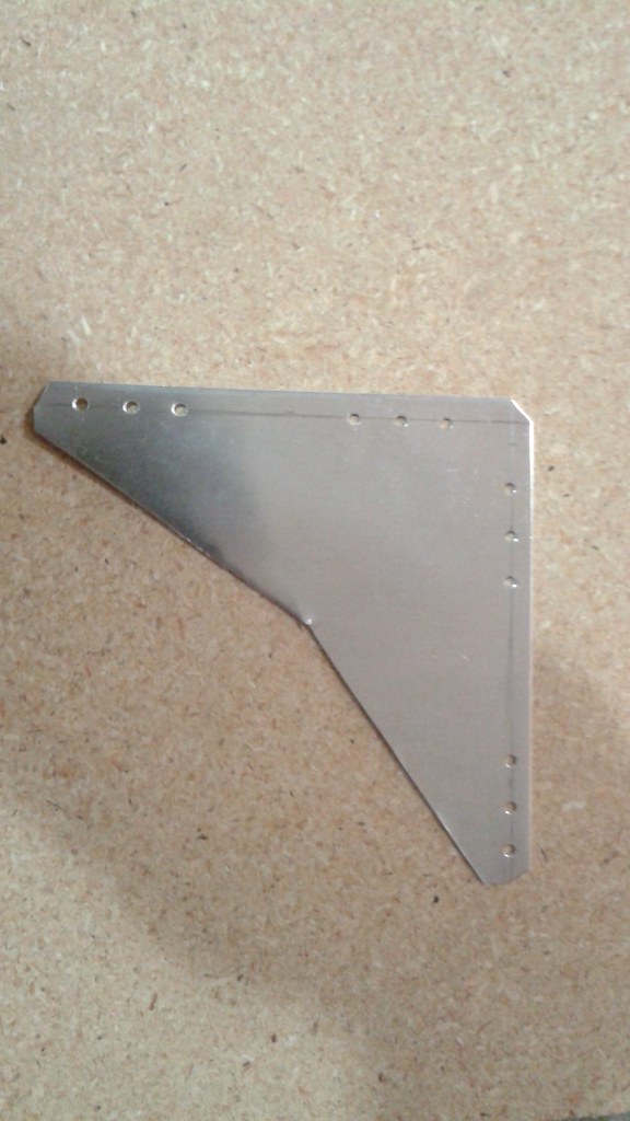
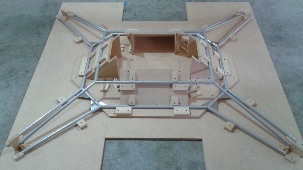
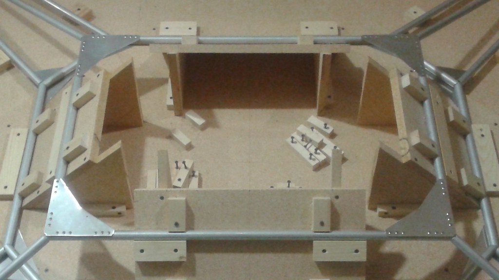
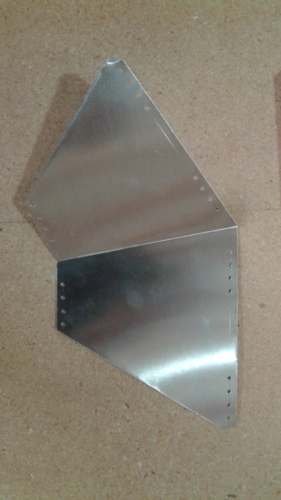
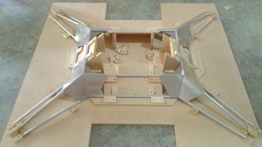
The Mk II frame is built using aluminum tube and assembled using aluminum gussets and and stainless steel rivets. This leads to a lightweight, vibration resistent design that can be assembled easily.

Engine

An electric powered design would have been the most straightforward approach. Electric motors are more efficient than gas motors, but the energy density of gasoline is much greater than today's batteries. So until battery technology improves, for large scale vehicles, gas power seemed the way to go.

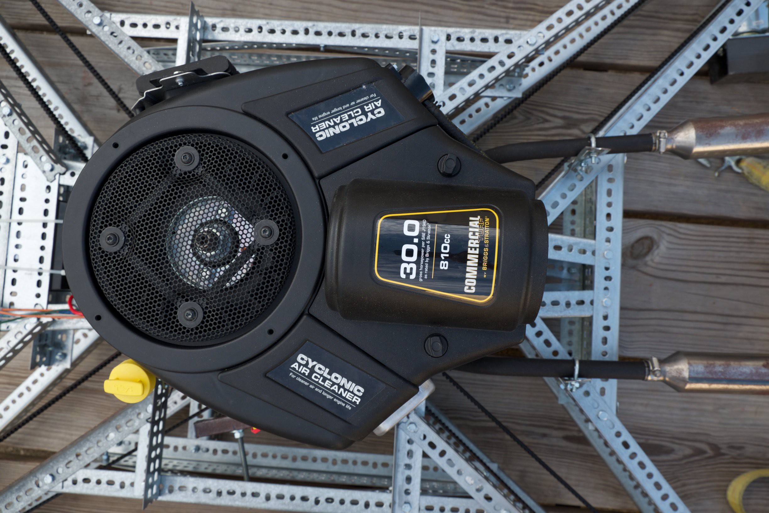
Goliath currently uses a single 30 Hp vertical shaft engine and a belt system to transfer power to the four propellers. The setup was chosen because at this scale, four smaller gas engines have a smaller power to weight ratio than a single larger engine. The specific engine, an 810cc Briggs and Stratton Commercial engine was chosen primarily because of its relative low cost per power ratio.

Drive System

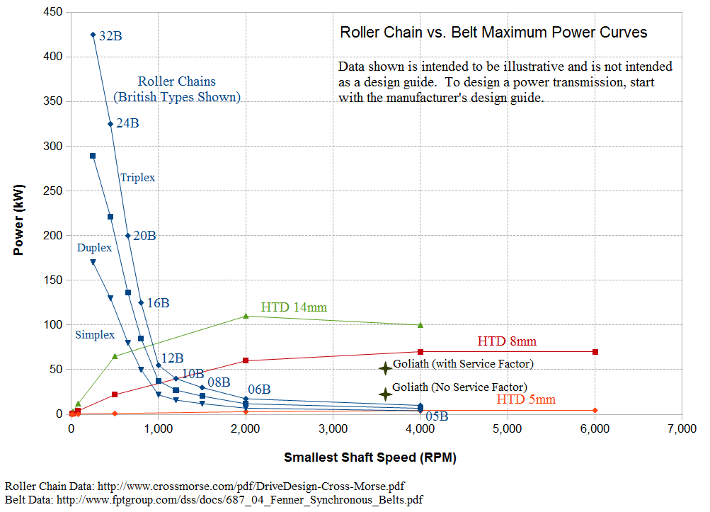
The drive system uses High Torque Drive (HTD) belts. These belts are made of neoprene rubber with continuous fiberglass cords. HTD belts are able to transfer more power per weight than roller chain and can also run at higher RPMs that Goliath requires.

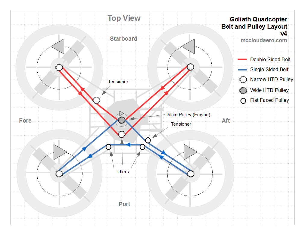
To eliminate aerodynamic torque, the drive system rotates two propellers clockwise (CW) and two counter-clockwise (CCW). This is done by using two belts, one sided sided and the second double sided. The direction of rotation is changed by placing the outside of the double sided belt against the driving pulley.

Propellers

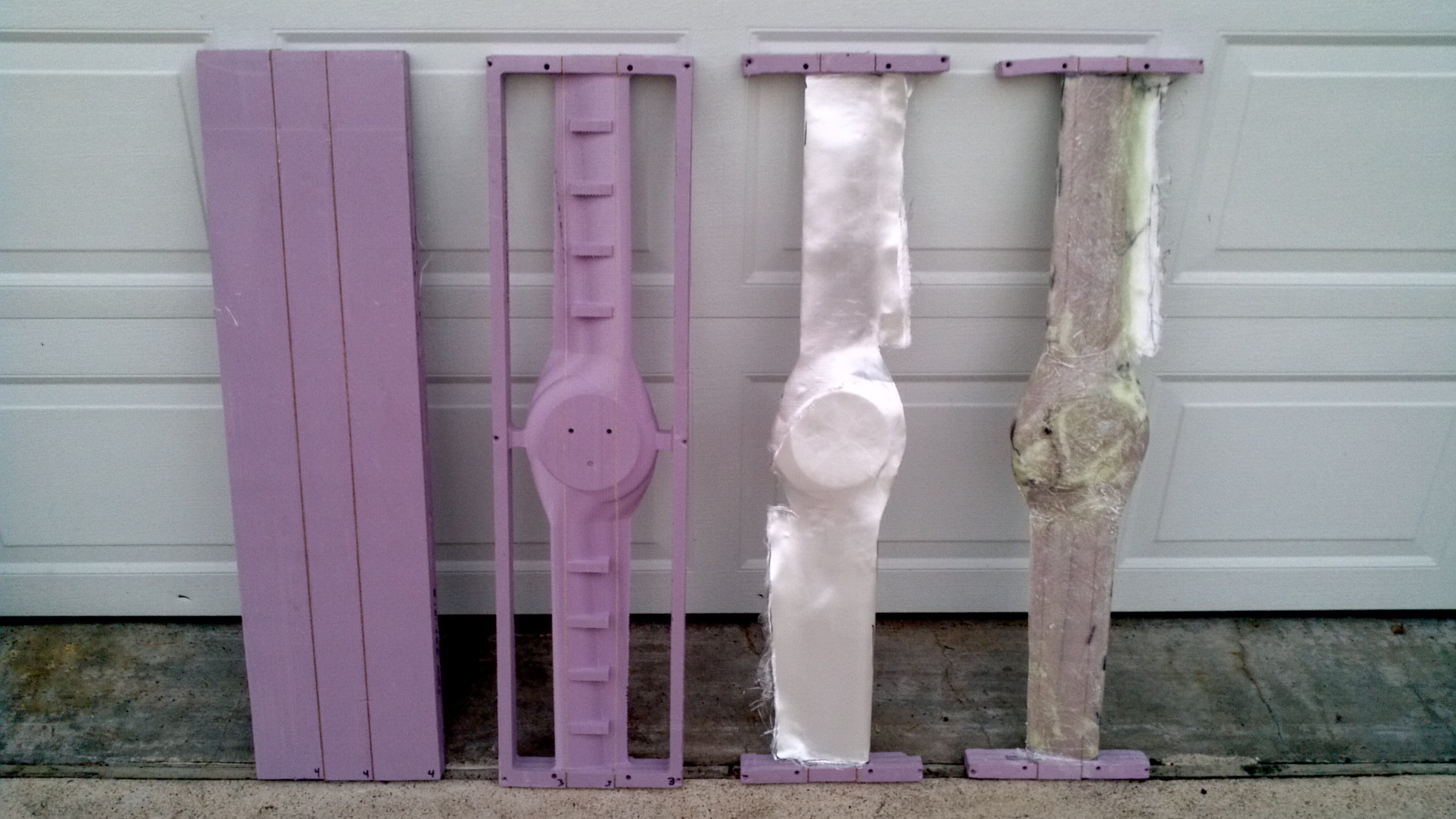
The propellers are fixed pitch propellers 36 inches in diameter. They are custom made, starting from a foam blank with birch stiffeners. The blanks are machined using a CNC router and then fiberglass and epoxy are laid up over the machined core. This process produces a propeller that can carry over 60 lbs while only weighing one and a quarter pounds.

Control

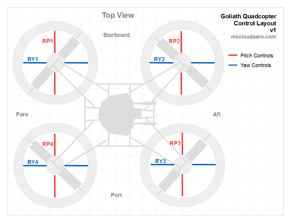
An electric quadcopter would traditionally maneuver by varying the speed of each propeller to control thrust. Since Goliath uses fixed pitch propellers and all the propellers turn at the same speed due to the belt drive, maneuvering will be done by control vanes similar to those used to steer hovercraft.

Exhaust

Each of the two exhaust pipes are built from Go-Kart hardware, which are easy to procure and inexpensive. The U-Build It Kits are easily assembled using a minimum of welding and highly customizable.

Electrical System

The electrical system is powered primarily from the alternator with the battery as a backup. The battery is 12V and designed for off-road vehicles, so it'll handle high vibration loads. The micro-controllers and servos...

Read more »

  • 1 × 30 HP vertical shaft gas engine Should equipped with a starter and alternator
  • 1 × Pixhawk Open Source Flight Controller
  • 2 × Clockwise Propellers (36" Diameter) See Detailed Build Instructions for Raw Materials (Forthcoming)
  • 2 × Counter Clockwise Propellers (36" Diameter) See Detailed Build Instructions for Raw Materials (Forthcoming)
  • 4 × Duct (37" Inner Diameter) See Detailed Build Instructions for Raw Materials (Forthcoming)

View all 22 components

  • Goliath Mk. III

    Peter McCloud06/05/2019 at 03:36 0 comments

    The hardware for Titan, Goliath's bigger brother is starting to come together. The engine has arrived and the first frame elements are taking shape.

    With Titan's design progressing, there's a need to test portions of the hardware before integrating the complete vehicle, particularly the rotors. Additionally, designing Titan has been educational, and some of the lessons learned can be applied to Goliath.  So this summer, work will start on upgrading Goliath to a Mk. III design with an update to the drive system and 42" rotors (vs. the previous 36" rotors).

    The #EVPR: Electric Variable Pitch Rotors will also receive a custom PCB designed by our very first intern. Things are falling into place to make a lot of progress this summer, so stay tuned.

    P.S. If are interested in progress updates specific to Goliath, check out McCloudAero.com  or follow us on LinkedIn

  • Goliath Expecting a Sibling in 2019

    Peter McCloud01/31/2019 at 18:57 0 comments

    Goliath is still moving forward, but work has already begun on the next vehicle that will incorporate the lessons learned from Goliath Mk. I and II. Over the past few months, I've been working on the conceptual design for the new vehicle, called Titan. The design has progressed to the point that today, the deposit was placed for the engine that will power Titan.

    It will be 3-4 months until the engine arrives and as the design matures, I'll be providing more details on the design. The goal is to have the vehicle assembled and begin testing by the end of 2019.

  • Pixhawk/PX4 Mixer Issues Among Other Things

    Peter McCloud11/14/2018 at 05:32 2 comments

    One of the advantages to using the Pixhawk is the ability to create custom control configurations. This is necessary for Goliath since it's using a single engine with variable pitch propellers. Previously, having a custom mixer  wasn't necessary since the standard quad mixer worked reasonably well with the variable pitch rotors as the PWM signals map in a similar manner. The downside to using the standard mixer is that the engine speed and thrust are not coupled, which made it difficult to control the engine RPM properly. Now that all four rotors are variable pitch, the thrust and engine speed need to be coupled together, making a custom mixer necessary.

    The process is supposed to be straightforward. You write a custom file, copy it to the SD card and update the configuration file on the SD card to point to the new mixer. After doing all that the rotors stopped working. After a lot of debugging and gnashing of teeth, it turns out there are currently some bugs in the PX4 build (https://github.com/PX4/Firmware/issues/8975).

    The workaround is to add the mixers to the Firmware source code, and flash the updated firmware to the PX4. Makes debugging a slower process as every time I want to make a change, I have to flash the firmware versus directly editing the file on the SD card, but it's working. The issue is supposed to be fixed in one of the upcoming releases, and things can hopefully go back to normal.

    At this point I was hoping to write that I have a new mixer file. Nope, that didn't happen. In the process of debugging the mixer, the Pixhawk is now refusing to arm, giving the error:

    PREFLIGHT FAIL: EKF INTERNAL CHECKS

    I've tried some of the easy steps to address this, but none of them worked. Since I can't arm, I can't test the custom mixer. So this needs to be addressed before I can finalize the mixer.

  • Dedicated Vehicle Mounts

    Peter McCloud11/02/2018 at 21:28 0 comments

    With a full set of #EVPR: Electric Variable Pitch Rotors completed, the next round of testing is getting close. One item on the to-do list to get ready is having dedicated vehicle mounts. In the past the vehicle was suspended by a loop of rope around the structural frame. Below is the previous setup.

    The issues is that the loops tend to move around, and when the ropes go slack, the rope ends can hit the rotors.

    With a brand new set of rotors, it'd be nice to keep them in good condition. So dedicated vehicle mounts were added.

    The mount is 1" wide and is the same thickness used on the gussets. The black material is a non-slip drawer liner material, to keep the parts from chafing.  No more movement of the mounts and no more impact issues with the rotors.

  • Portland Maker Faire Sept 15th and 16th

    Peter McCloud09/01/2018 at 18:07 0 comments

    Goliath will be on display at the Portland Maker Faire at OMSI on Sept. 15th and 16th. The vehicle has a full set of  #EVPR: Electric Variable Pitch Rotor installed. In addition to the Mk. II vehicle, we'll also have the Mk. I frame on display.

  • OMSI Robot Weekend June 16th and 17th

    Peter McCloud06/01/2018 at 20:00 0 comments

    In the Pacific Northwest and want to see Goliath Mk. II or the #EVPR: Electric Variable Pitch Rotor in person? Come out to OMSI's Robot Weekend on June 16th and 17th. This will be the first time Goliath is displayed with all of the controls integrated into the vehicle. The last of the variable pitch rotors has been assembled and is ready to go on the vehicle.

    Below is a photo with the first two variable pitch rotors mounted.

  • Flight Controller Died, Looking For a New Controller...

    Peter McCloud06/23/2017 at 03:58 5 comments

    Progress is being made the flight controls and the hub for the first prototype was attached to Goliath and spun up to make sure it held together (see #EVPR: Electric Variable Pitch Rotor for more details). There were no issues with the EVPR, there was an issue with the flight controller. When the vehicle was activated, the controller didn't power up properly. The Pixhawk consists on an FMU and an IO board. The IO board power was the only light coming on, nothing else. As a work around for this test, the flight controller was removed and I went back to controller the throttle with just a standard RC receiver directly connected.

    While I can do a little bit more testing without the controller, it's not going to be too long before I need a new controller to start testing the interface between it and the EVPR. However, I'm a little hesitant to get another Pixhawk as I'm not sure what went wrong with the old one. It was about 3 years old, but there was only a handful of hours on it. There were a few rough tests, before I nailed down the isolation on the avionics tray and Goliath had two solenoids go bad, most likely due to vibration.

    I'm familiar with the PX4 flight stack and at least know conceptually how to proceed with modifying the software to work with the EVPR. However there a few controllers that use the PX4 stack including the newer Pixhawk 2.1. Of course it uses different connectors, so the stack of DF13 connectors I have laying around as well as the GPS would be worthless, but maybe it makes sense to upgrade.

    If anyone has any thoughts I'd love to hear them.

  • Control Hardware Starting to Take Shape

    Peter McCloud03/27/2017 at 02:42 0 comments

    Up till now the work on Goliath has concentrated the drive train and the structure. The controls were put on the back burner until the other design problems were addressed. The other items aren't done, but the project has progressed to the point that having a control system would be helpful.

    When Goliath was originally conceived three years ago, the default control scheme was to use vanes underneath the rotors to direct the airflow for control. This was chosen because it was the simplest hardware setup to implement and it's been demonstrated to work for hovercraft. Back in October I started doing some basic calculations to size the control vanes and determine the required servo sizes. Turns out assuming that if it works for a hovercraft, it'll work for Goliath was a bad assumption.

    The issue with using vanes is the rotor downwash velocity. Goliath has a similar amount of horsepower as a hovercraft, but instead of 1 fan, there are 4 rotors, so the power per area is reduced by a factor of 4. Additionally the equation for the force generated by a vane is:


    So if the downwash is reduced by a factor of 2, the force created by the vane is decreased by a factor of four. The end result is that at full thrust, a single vane would have generated only two pounds of force. Which would be grossly inadequate. More force can be generated using multiple vanes in parallel, but the forces would still be low.

    I was discussing this issue with @Benchoff at the OSHW summit, and he suggested using grid fins instead. Doing some back of the envelope calculations show that grid fins should generate enough force. The downside is that the the grid fins have much higher drag, which would reduce the payload or flight time.

    Ignoring their complexity, variable pitch rotors would be the ideal control scheme. Variable pitch rotors would be able to generate larger moment torques than either vanes or grid fins. However, the increased complexity and the fact that Goliath is already a complex project, convinced me not to pursue this.

    However, it's been three years and I really want to see Goliath fly, so I've decided to start building both grid fins and a variable pitch rotor. If I pick one scheme and it doesn't work, then it'll be that much longer before it can fly. So I'll incrementally develop both and see which one works out better.

    Grid Fins

    The grid fins I'll document as part of Goliath as they are relatively straight forward. I have sourced some material to create the fins. The fins will be made from aluminum louvers for florescent lighting. It was difficult finding sheets big enough to make a 36" disc from, but I finally found some 4'x4' sheets (shown below).

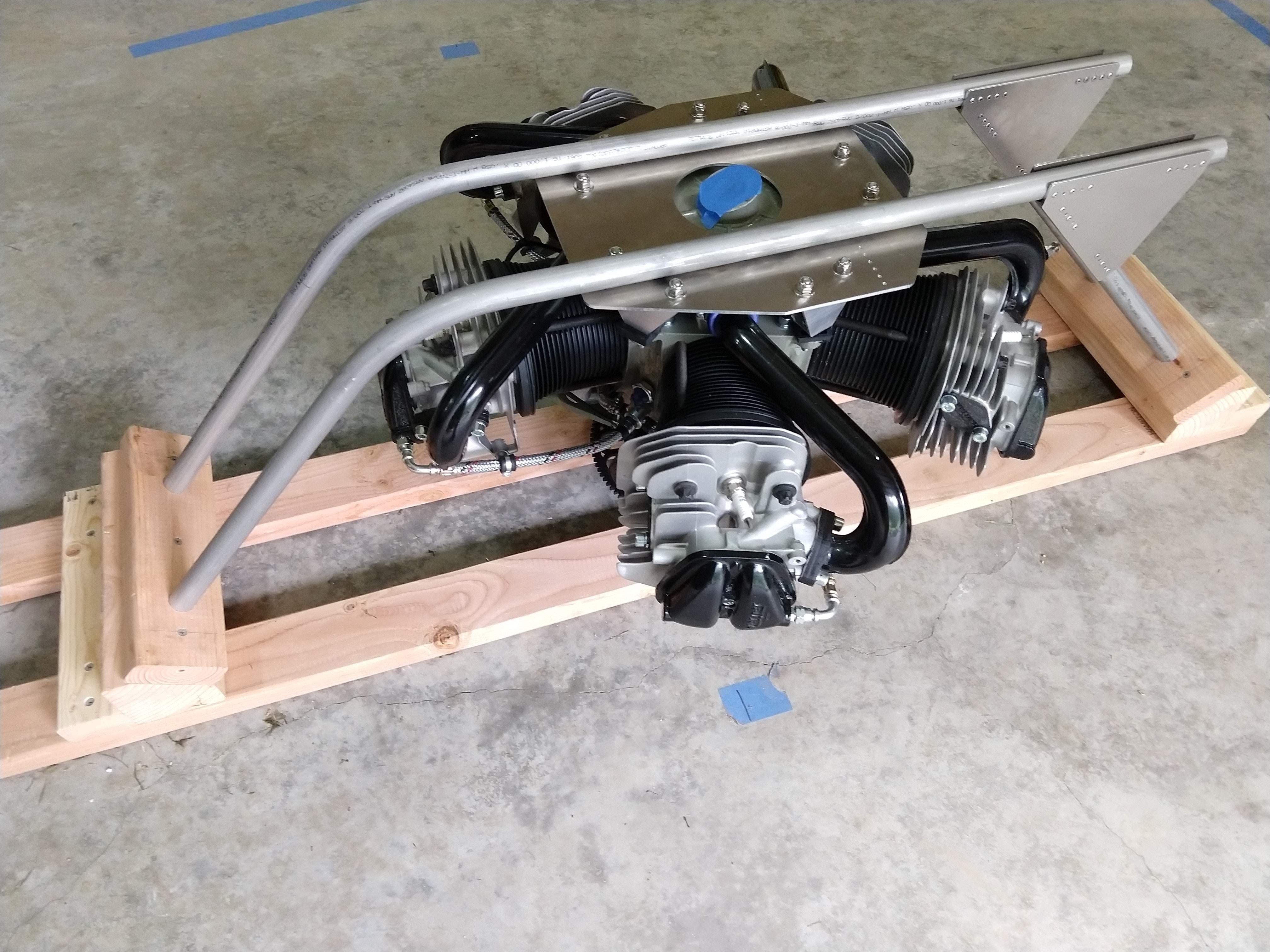
    The next step will be cutting out a test disc and placing it under a rotor to determine the control forces generated.

    Variable Pitch Rotors

    The variable pitch rotors are a different story. I had decided not to pursue this until I came across some research that made me realize that it may be possible to create an electrically actuated variable pitch rotor with the servos contained inside the rotor hub.

    I've created a separate project, #EVPR: Electric Variable Pitch Rotor, and I'll be documenting the progress there. I'll be populating more of the design details there, be sure to follow the project if you're interested and want to get updates. Additionally, I think that the project can be useful for other multi-rotors and even conventional aircraft, so I'm entering #EVPR: Electric Variable Pitch Rotor in the 2017 Hackaday Prize. If you think it's worthwhile, but sure to give it a like.

  • Evaluating Aerodynamics

    Peter McCloud03/12/2017 at 00:26 0 comments

    Goliath hovered for the first time in September of 2016. The hover performance was less than desirable since it required a higher throttle setting than hoped and the vehicle did not rise evenly. It tended to favor the port side or the aft. Even more puzzling, was that it tended to lift off first on the side that had the most weight. Ballast could fix the issue, but understanding why is also important. Testing has continued to evaluate the aerodynamics of the setup. Below is a video compilation of some of those tests.

    Test 12 was a simple flow visualization of the rotor downwash. Tufts of yarn were added to the frame to show the flow direction along the radius of the rotor and into the frame. The tufts behaved as expected, with the tufts under the rotor mostly steady. Inside the frame, the tufts indicated the flow reversed and flowed upward due to ground effects. While the tufts wiggled, there did not appear to be anything that suggested any unsteady flow phenomena.

    Tests were also conducted outside to see if the shop walls and ceiling were effecting the aerodynamics. Occasionally in the past, loose debris had been ingested into the rotors and the debris recirculated inside the wake as the flow got turned around by the walls and got re-ingested. Testing outside reduced the re-circulation.

    Test 16 nearly ended up with the vehicle getting damaged. There were four hold-downs, intended to allow the vehicle to move slightly upward, yet remain captive. They weren't made long enough and the hold-downs failed on the aft end of the vehicle. Fortunately, the throttle was reduced in time and the vehicle settled back on the stand (albeit precariously).

    The hold-downs were fixed and the testing continued. During Test 17, the vehicle again lifted up, favoring the port side, but at a reduced throttle setting. However, the test stand didn't allow enough movement for a full hover to be achieved. The test showed that the asymmetries were present, regardless.

    In theory, the rotors themselves should have been out of ground effect as they were at least one diameter above the ground. However, for quadcopters, it may be that the ground effect is dependent on the length scale of the four rotors together and not the length scale of a single rotor. If that is true, then perhaps the port rotors are experiencing higher thrust since they are slightly closer to the ground. It's difficult to tell exactly. This may be why the Mallory Hoverbike has the offset rotors catty-corner from each other.

  • Mitigating the vibrations

    Peter McCloud12/12/2016 at 05:04 0 comments

    I'd hoped to be well into working on the controls on Goliath by now, but the shorter days and colder weather mean less time in the shop. I'm still nailing down some lingering issues with the drive train. The new pulleys are weeping grease because the bearings are getting too hot. I suspect it's because I'm using all thread axles and nuts to keep the bearings in place. I'm working on building the proper axles and axles mounts to go with the new pulleys.

    Meanwhile I wanted to document the progress made on mitigating the vibrations that the avionics experience. This was accomplished by better isolating the engine from the frame and the avionics tray from the frame. The new engine mounts are made primarily of rubber, but are built such that if the rubber fails, the bolts are still captive. Stainless steel bolts are used to attach the mounts.

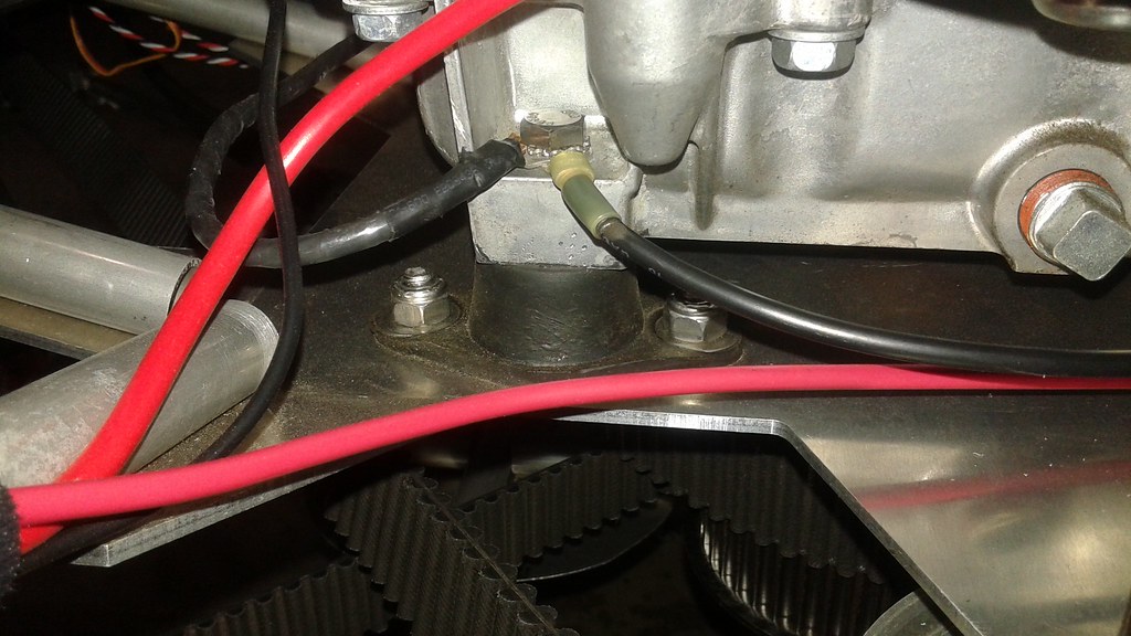
    The avionics tray was switched from aluminum to steel. This was to add mass to help reduce the displacement of the avionics tray. Below is the new tray with some of the avionics populated.

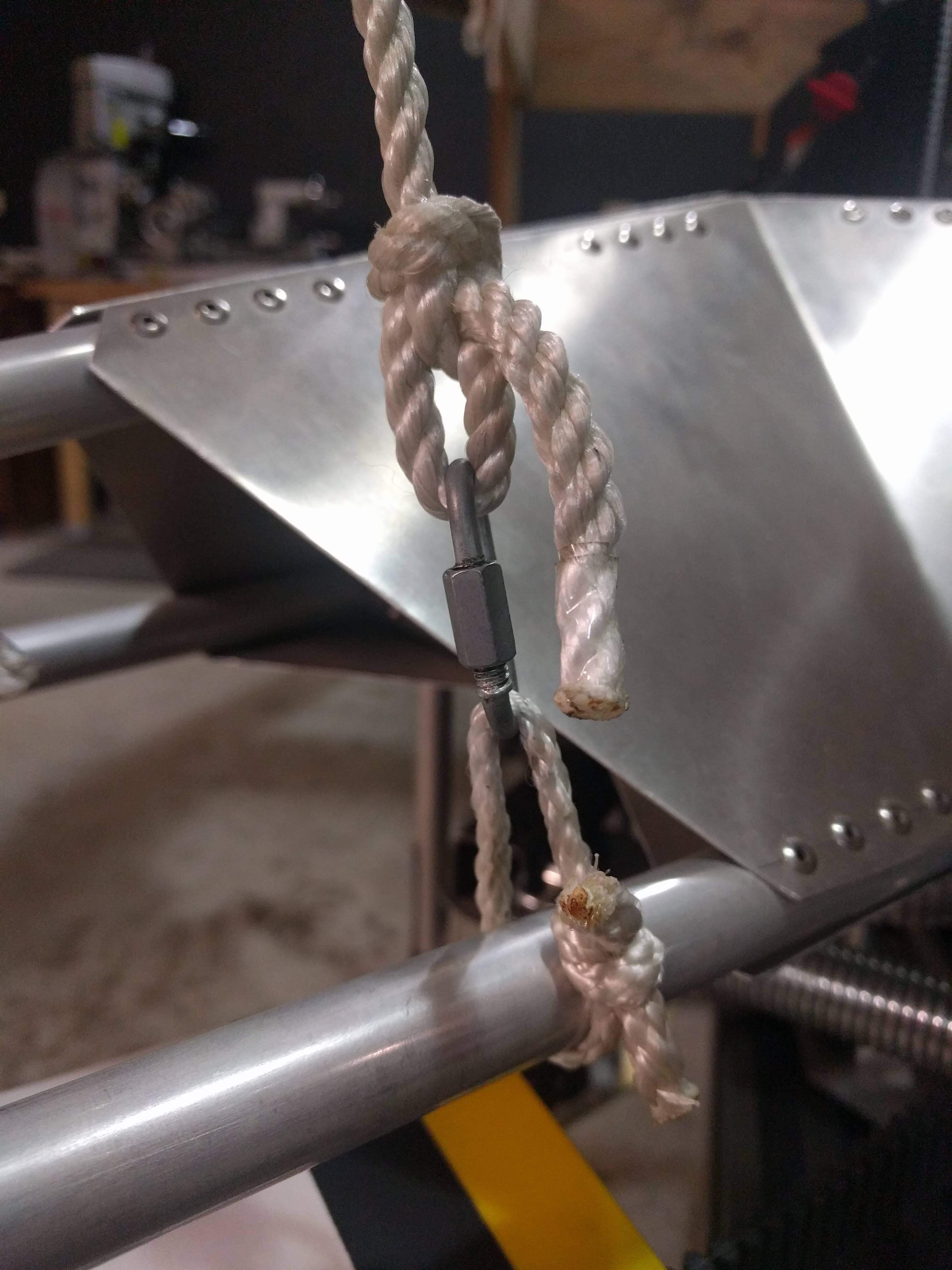
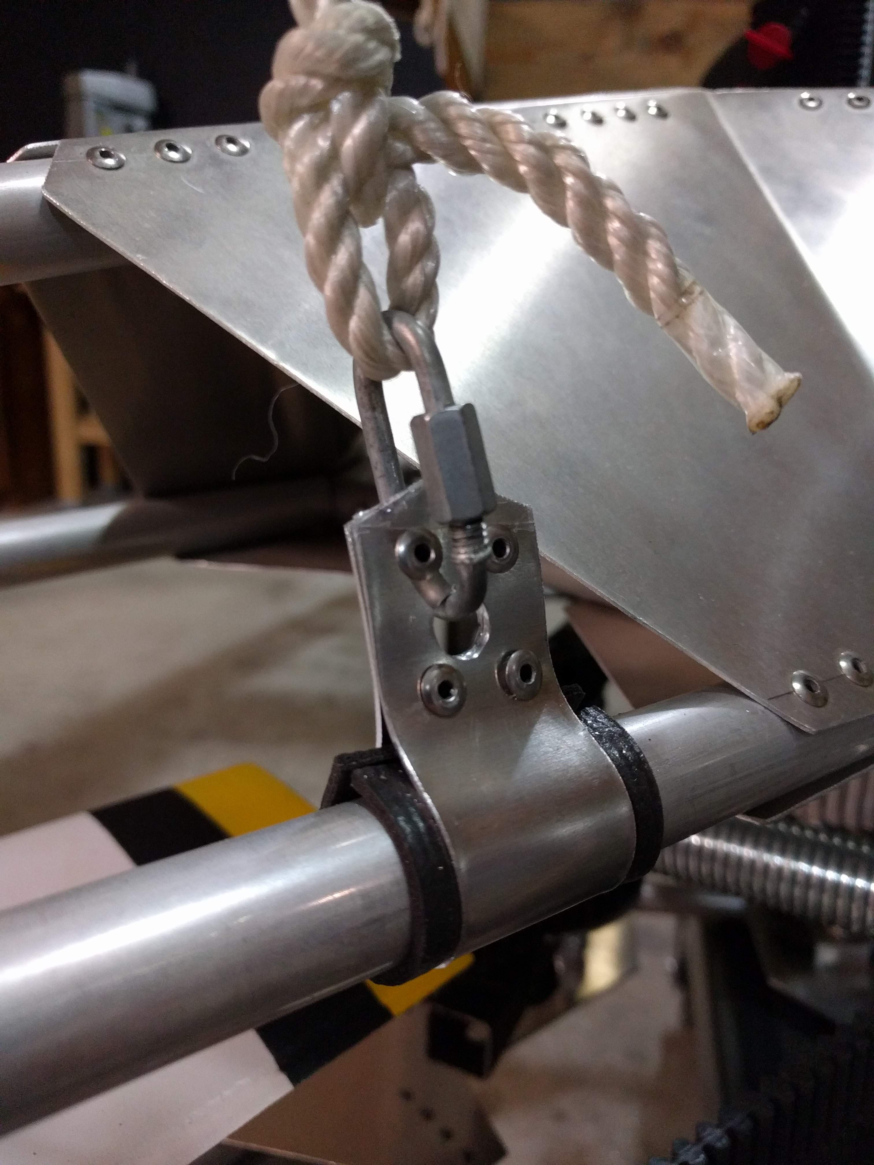
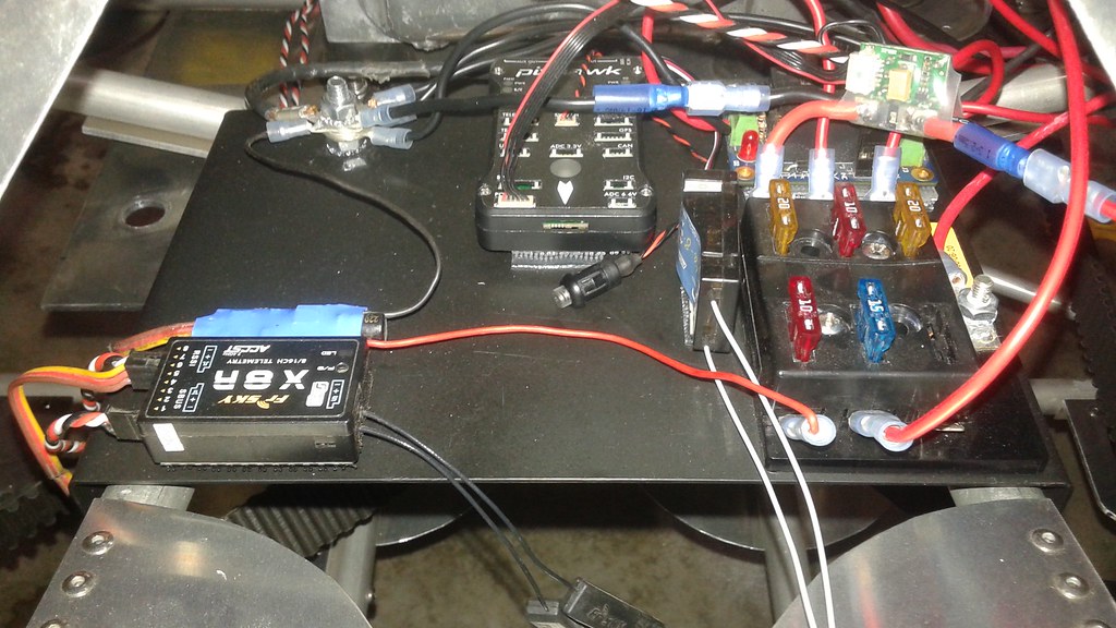
    The tray is mounted to the frame using four Expansion Nuts. I forgot to take a picture of them before I installed them, so here is a link. Below is a shot showing the flange on the expansion nut between the tray and the frame.

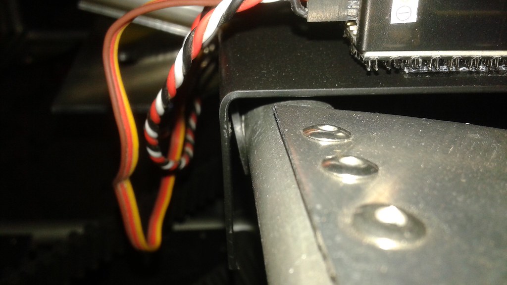
    So how much did all the changes help? Data from the Pixhawk shows a huge reduction in the pitch rates down by a factor of 5 to 10. This means that the Pixhawk should be able to control Goliath once the rest of the hardware is complete.

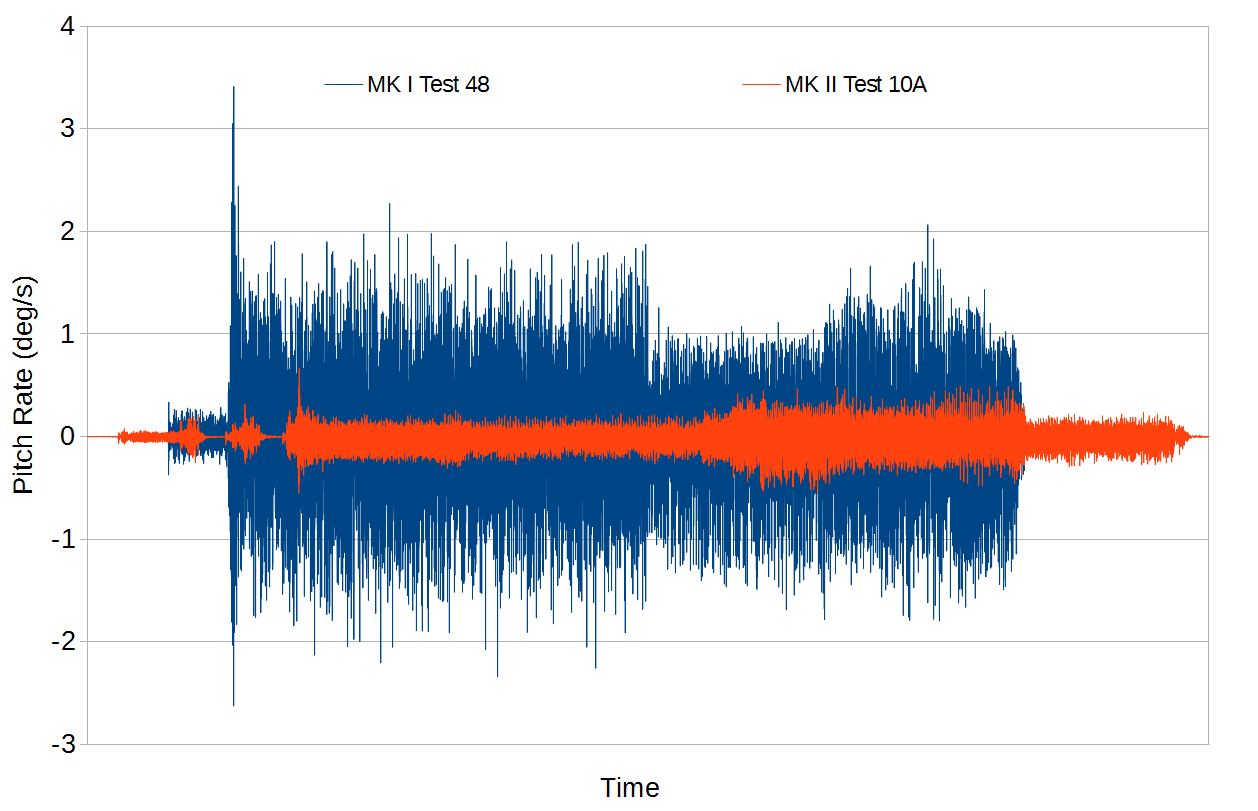
    Hopefully the next log update in the not too distant future will be about fixing the bearing issues.

View all 79 project logs

  • 1
    Step 1

    THINK BEFORE YOU START

    Before you start this project, take some time to REALLY think about what you're about to build. Seriously, this is a flying machine that weighs more than most people and runs on gasoline, a chemical that the states of Oregon and New Jersey have deemed too dangerous for the average citizen to pump into their own car.

    While Goliath is a big and powerful, it's only as dangerous as the user. As you build, test and fly your giant quad copter be mindful of your safety and the safety of others.

  • 2
    Step 2

    BUILDING THE COMPOSITES

    Building the composite pieces requires the longest amount of lead time. It's recommended to start these pieces first, and the rest of the components likely be built while waiting for the composite pieces. Components made from composites are:

    • Propellers
    • Ducts
    • Control Surfaces
  • 3
    Step 3

    BUILDING THE UPPER FRAME

    Tools - Miter Saw, Jig Saw or Tin Snips, File, Drill with #30 drill bit,Rivet Puller

    A) Build the Jig for the Upper Frame

    To properly build the frame, jigs are required to hold all of the frame elements in place. The jig is constructed from particle board. Below the completed jig is shown with the upper frame elements in place.


    B) Cut the Upper Frame Elements

    Using a miter saw, cut all of the frame elements and place them in the jig to ensure a proper fit.

    C) Cut the Common Gussets

    Cut the common gussets (4 A & 4 B), layout and drill the holes with the #30 drill bit.


    D) Assemble the Upper Deck Elements

    1) Remove the frame elements for the upper ring, leaving just the pieces for the upper deck


    2) Clamp the common gussets in place and drill half of the holes into the frame. Use Clecos to fill in the holes as you go.

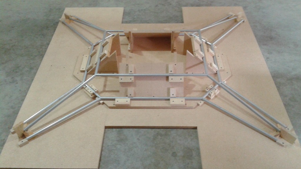
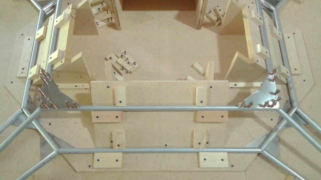
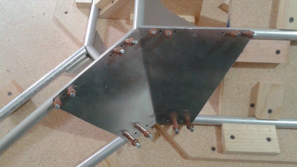
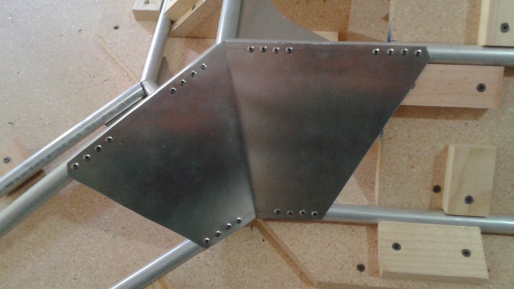
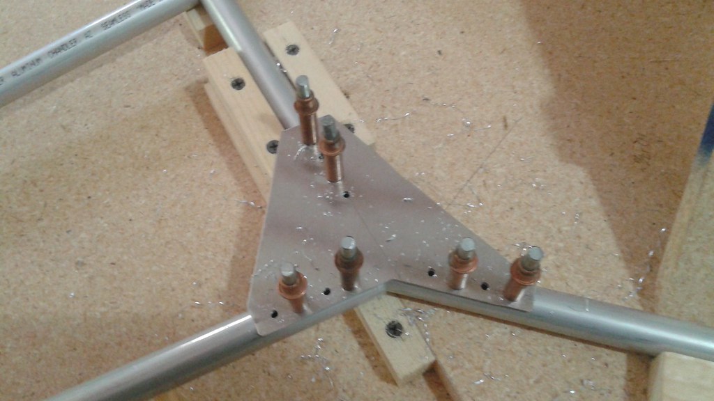
    3) With half of the holes filled with Clecos, drill the remaining holes and fill them with rivets.
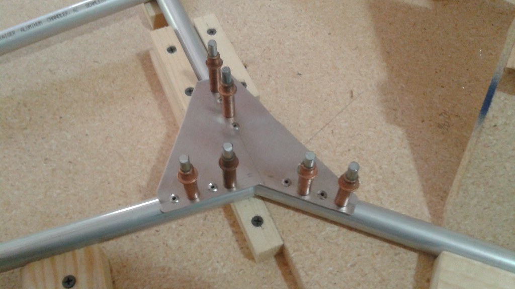

    4) Remove the Clecos and fill in the remaining holes with rivets.

    5) Remove the upper deck from the jig, flip it over and place it back in the Jig

    E) Cut the Corner Gussets

    F) Assemble the Upper Ring

    1) Place the remaining frame elements back in the Jig

    2) Attach the corner gussets


    G) Join the Upper Ring to the Upper Deck

    1) Cut the Angle Gussets


    2) Attach each of the angle gussets


    The Upper Frame is now complete and can be removed from the Jig


View all 11 instructions

Enjoy this project?

Share

Discussions

Steve Shaffer wrote 08/07/2014 at 18:34 point
Invent a pulley that can expand and contract by turning something. This will give you prop speed control, and thus allow simple control by all the normal RC control baords.

  Are you sure? yes | no

Peter McCloud wrote 08/08/2014 at 14:36 point
That would certainly make things easier. CVTs use a conical pulley to adjust the radius to do what you're talking about, but I don't think it'll work with a toothed belt. An expanding and contracting pulley would have to allow the teeth to slip in some manner. Perhaps a Derailleur setup might work, but I don't think it'd be responsive enough.

  Are you sure? yes | no

Steve Shaffer wrote 08/08/2014 at 14:54 point
I agree it's hard. The more I read the others comments the more it really sounds like you should spring for 1/5th scale helicopter assemblies and blades, then simple servos can adjust pitch and therefore thrust just like an electric quadcopter. I just created a guided rocket powered by the 4hp edf from Dr. Mad Thrust, with vectored thrust by flaps, flaps suck, couldn't get stabilization good enough with the multiwii controller. Just a heads up. I've given up with flaps for good thrust vectoring and am changing the design of the craft and giving it swivel nozzle styled vectored thrust.

  Are you sure? yes | no

zakqwy wrote 08/09/2014 at 01:42 point
Steve, I'd like to see your project if you do a gimbaled thruster. In my experience, it's not easy.

  Are you sure? yes | no

Stephane wrote 07/07/2014 at 19:52 point
For the propellors; when I built my composite uav wings I used the scraps from the hotwire cutting as a support for vacuum bagging. Since you mill your cores you may want to mill shells that fit around the props when bagging? Also some UD carbon on both sides of the prop will increase the bending strength :)

  Are you sure? yes | no

Peter McCloud wrote 07/08/2014 at 00:20 point
Thanks! Milling support shells sounds like a good idea. I do plan on eventually switching to carbon to increase the strength, but I'd rather get all the kinks worked out with cheaper fiberglass.

  Are you sure? yes | no

PK wrote 07/03/2014 at 21:35 point
Awesome project! Would love to see it fly.

  Are you sure? yes | no

Peter McCloud wrote 07/05/2014 at 03:09 point
Thanks! I'm looking forward to seeing it fly too!

  Are you sure? yes | no

pfeffer.marius wrote 07/03/2014 at 17:55 point
Whats your current plan for thrust control ? You could use some kind of wing, controlled with a (big) servo which can increase its produced air resistance under a rotor. (like flaps on a airplane)

  Are you sure? yes | no

Peter McCloud wrote 07/05/2014 at 03:22 point
Thanks for the inputs! The current plan is to use vanes similar to how hovercraft steer. That'd be a good way to control pitch and roll, but I'm not sure how well that'd work for yaw.

  Are you sure? yes | no

WillyMacD wrote 06/22/2014 at 00:41 point
Peter, I'm planning a similar albeit, smaller project. For thrust control, I was bouncing the idea of using electrically controlled clutches on the shafts of the props. Perhaps this is something that may work for you as well as with minimal changes to current control software. cheers and good luck

  Are you sure? yes | no

Peter McCloud wrote 06/22/2014 at 03:42 point
Thanks for the input! I'd really be interested in hearing more about your project if you feel like sharing. I don't know much about electrically controlled clutches but I'm definitely intrigued. The control system isn't set yet so it's a possibility. Do the clutches act simply in an On/Off manner or can you vary much much they engage?

  Are you sure? yes | no

Christoph wrote 06/21/2014 at 08:57 point
Ever thought about using the fuel engine as an electic generator? I understand that's not really helpfull at this point, but in my opinion thats a better way to go. Im curious about the flight dynamics of a mechanical sytem like yours. Maybe you add some serious nonlinearities to the system regarding control theory. ... Or maybe it'll just fly as heck. Have fun.

  Are you sure? yes | no

Peter McCloud wrote 06/22/2014 at 03:26 point
I had thought about coupling the gas engine with an electric generator and then using electric motors (hybrid system), but it's just too heavy at this scale. For aircraft the engines run near the optimum RPM most of the time, so the advantage of a hybrid system isn't as great.
I'm really curious as to how the controls are going to behave as well! I'm not expecting Goliath to be very nimble, but we'll see. Thanks for the feedback!

  Are you sure? yes | no

samern wrote 06/19/2014 at 03:15 point
You might consider emulating what you see in an ordinary A/C outlet in a car....3 or 4 vanes controlled by a single horn sitting outside the duct. Air can flow down the duct and then down and the vanes can direct the air straight down, or horizontally perpendicular to the quad's arm/duct. That gives you pitch/roll and yaw. the degree the vanes move controls the vectored force at the edge of the arm and so altitude and direction. You can also control airflow through the duct with a butterfly valve inside the duct also controlled by a horn (someone mentioned that as well, I think). What I think is going to be super interesting is the flight control software...

  Are you sure? yes | no

samern wrote 06/18/2014 at 20:01 point
Did someone already suggest this....I know you are using fixed pitch props, but there have been developments with constant speed props that don't use a governor and use small electric motors to vary pitch. Might make this too complicated and heavy. If you consider ducts you are going to need quite the concentrated blast out of each tip. The Harrier uses a rotating valves with vanes to vary the thrust direction, you might get some value out of just nozzles that open and close out the end....at any rate this is so very interesting I'm looking forward to seeing it fly.

  Are you sure? yes | no

Peter McCloud wrote 06/19/2014 at 01:36 point
Thanks for the feedback! I've been really hesitant to look into variable pitch props. Maybe I'm just biased towards the fixed pitch for simplicity, but one big concern is the loading. Each blade will be supporting 30 lbs in hover, which will provide a large moment at the blade root and make any variable pitch hardware heavy.
I really wanted to have the ducts be part of control system and opening and closing the nozzle at the end of the ducts would be a great way to do that. I'm just not sure how to implement it. I had thought about using nitinal wire to expand and contract the nozzle, but I'm not sure how responsive it would be.

  Are you sure? yes | no

Adam Fabio wrote 06/12/2014 at 02:46 point
Wow! that's one big quadcopter - thanks for submitting Goliath to The Hackaday Prize! I'm just curious how you'll get the props spinning in opposite directions to avoid torque issues?
Keep up the good work, and don't forget to document your flight control system - I'm curious to see what sort of system you go with - vanes and servos or something completely different!

  Are you sure? yes | no

Peter McCloud wrote 06/12/2014 at 10:57 point
Thanks! I'm planning on posting about the drive system later today and that'll show how the props spin in opposite directions.
I think that vanes and servos might be the best choice. All the other methods I've considered wouldn't handle yawing the vehicle well since all of the propellers rotate at the same speed.

  Are you sure? yes | no

RoGeorge wrote 06/09/2014 at 22:40 point
Did you considered Continuous Variable Transmission http://en.wikipedia.org/wiki/Continuously_variable_transmission instead of a gearbox?

It might help with the thrust distribution too.

  Are you sure? yes | no

Peter McCloud wrote 06/10/2014 at 22:16 point
I had not considered a CVT. Goliath doesn't have a gearbox, but it does use belts. Maybe a CVT could be used to vary the propeller speeds. Thanks for the suggestion!

  Are you sure? yes | no

jeff.ballard.86 wrote 06/04/2014 at 01:12 point
This sounds so dangerous/awesome, those two words do go hand in hand you know. :D

Im gonna pay attention to this, I may have to recreate your results when you finish.

  Are you sure? yes | no

Peter McCloud wrote 06/06/2014 at 22:13 point
Thanks, I'm glad to hear someone else is thinking about building their own!

  Are you sure? yes | no

dave.m.mcdonough wrote 05/28/2014 at 00:50 point
How to you plan on adjusting the thrust vector? Considering the belt drive I would think adjustable pitch props would be WAY easier mechanically, and provide more controllable result.
Also check out fiberglass poles for windsocks and such, using ones as a driveshaft inside a larger one as the support might be a lot lighter than a frame rigid enough to handle all that belt tension and let you space the props out further.
Or possibly even just using the engine as a generator and plopping electrics on the corners. ;)
Looks like you're already well underway but I hope the ideas help.

  Are you sure? yes | no

Peter McCloud wrote 05/28/2014 at 11:34 point
Thanks for the inputs! I had looked into driveshafts and while the fiberglass would be light, I'd need gearboxes at the center and at the propellers. I was really hoping to build a gas/electric hybrid since control would be simpler with electrics at the propellers, but I think the quadcopter would have to be even bigger before you can carry a generator and motors to go with it.
As for the thrust vectoring I haven't decided for sure yet, but I'm currently thinking servo actuated surfaces or something integrated with the ducting.

  Are you sure? yes | no

zakqwy wrote 05/28/2014 at 12:22 point
I've been doing a lot of design work trying to optimize thrust:weight ratio; while I plan to do some real-world tests to validate prop and motor selection, this site has given me a good quick starting point:

http://personal.osi.hu/fuzesisz/strc_eng/

It allows you to input prop size, pitch, type, air density, amd RPM and spits out a thrust calculation and motor power requirement. I haven't dug in to the tool's calculations, but it may be a good starting point for you. I'm guessing your belt-driven design will give you plenty of alignment flexibility but will also limit your maximum RPM, requiring a fairly good size set of props.

It's worth mentioning: 30 HP is A LOT of power. I suggest doing some research on typical maximun safe belt RPMs and using this as a primary design constraint to minimize safety concerns; in addition to whipping about and damaging stuff, a broken drive belt would likely result in a catastrophic and unrecoverable loss of flight control. Might be worth taking the weight penalty to equip the chassis with some kind of belt guard.

  Are you sure? yes | no

dave.m.mcdonough wrote 05/28/2014 at 12:46 point
So I'm looking at this project log of the motor with it's cover off and I got an interesting idea. This is a little off the wall and mostly half-baked brainstorm kinda thing but maybe you can think about it.
instead of a frame, belts, pulleys, etc.. mount the biggest blower fan 30HP can support directly to the motor. Then construct the frame as a big hollow X shape where the air gets ducted out the corners. maybe some in the center too but the corners will have your airflow vane directional vectoring control going on. Like a big hovercraft thing. :D
Just wrapped fiberglass or something would be pretty lightweight.

  Are you sure? yes | no

zakqwy wrote 05/28/2014 at 15:44 point
Cool idea, Dave. Isn't that how the Harrier and the VTOL version kf the F35 work? Definitely easier to actuate louvers then props; in addition to maintaining belt tension during vectoring you'll need to consider gyroscopic effects of the spinning props, which might drive up actuator torque requirements.

  Are you sure? yes | no

dave.m.mcdonough wrote 05/28/2014 at 15:55 point
Harrier turns the turbine exhaust straight downwards so yes kind of similar to that but we wouldn't be having a forward facing intake.. F35 I think has a separate turbine for VTOL? Not sure.
It occurred to me that in this x shape ductwork thing you could also have some throttle-body style valves to proportion the outputs.

  Are you sure? yes | no

zakqwy wrote 05/28/2014 at 16:37 point
Yup, butterfly valves of some kind would work. Turndown isn't great but they would only need enough rangability for angular velocity changes; overall ascent rate could be controlled using engine speed and maybe trimmed for response using the dampers. I'll bet you could actually salvage the throttle plate mechanisms out of a few old engines, the basic design requirements are likely similar.

  Are you sure? yes | no

Peter McCloud wrote 05/29/2014 at 23:05 point
Thanks for the link to the information, I'll have to check that against what I've calculated so far. Yes 30HP is ALOT, but the frame and ducting will encompass the belting. Once I go beyond tethered flying, I plan to incorporate a Ballistic Recovery System to help with any failures.
Also interesting idea with the blower and jetting the exhaust. I'm not sure if that method would work with this engine's weight and power though.

  Are you sure? yes | no

zakqwy wrote 05/26/2014 at 06:36 point
Are you using some kind of swashplate system? How are you varying prop pitch? This is quite awesome.

  Are you sure? yes | no

Peter McCloud wrote 05/26/2014 at 13:40 point
The plan is to use fixed pitch props and to vary the thrust direction for control. The controls haven't built yet, and there are a few methods I'm considering using. Thanks for the interest in the project!

  Are you sure? yes | no

zakqwy wrote 05/26/2014 at 13:52 point
Cool! We should compare notes, I'm putzing about with gimbaled fans albeit on a far smaller scale. Looking forward to seeing your design.

  Are you sure? yes | no

Similar Projects

Does this project spark your interest?

Become a member to follow this project and never miss any updates