 Peter McCloud
The Goliath design started back in November of 2013. The project goals were:
1) Build a gas powered quadcopter
2) Use parts that are easy to obtain (as much as possible)
3) Use parts that don't require specialized skills to build (as much as possible)
4) Create a design that could be scaled up.
Prior to starting this project a number of paper design iterations were done, researching various methods of building a gas powered quadcopter. After looking at a number of power configurations (single engine, multiple engines, hybrid gas/electric and a hybrid gas pneumatic) as well as drive train options (belt, chain, gearboxes with drive shafts, etc). For the size of vehicle chosen the best power to weight option was a single vertical shaft gas engine with a belt drive. By using a vertical shaft engine, the shaft is already aligned with the propeller axes and the need for complex gearing goes away. The belt drive has the advantage that it's lightweight, shock resistant and can be easily scaled up.
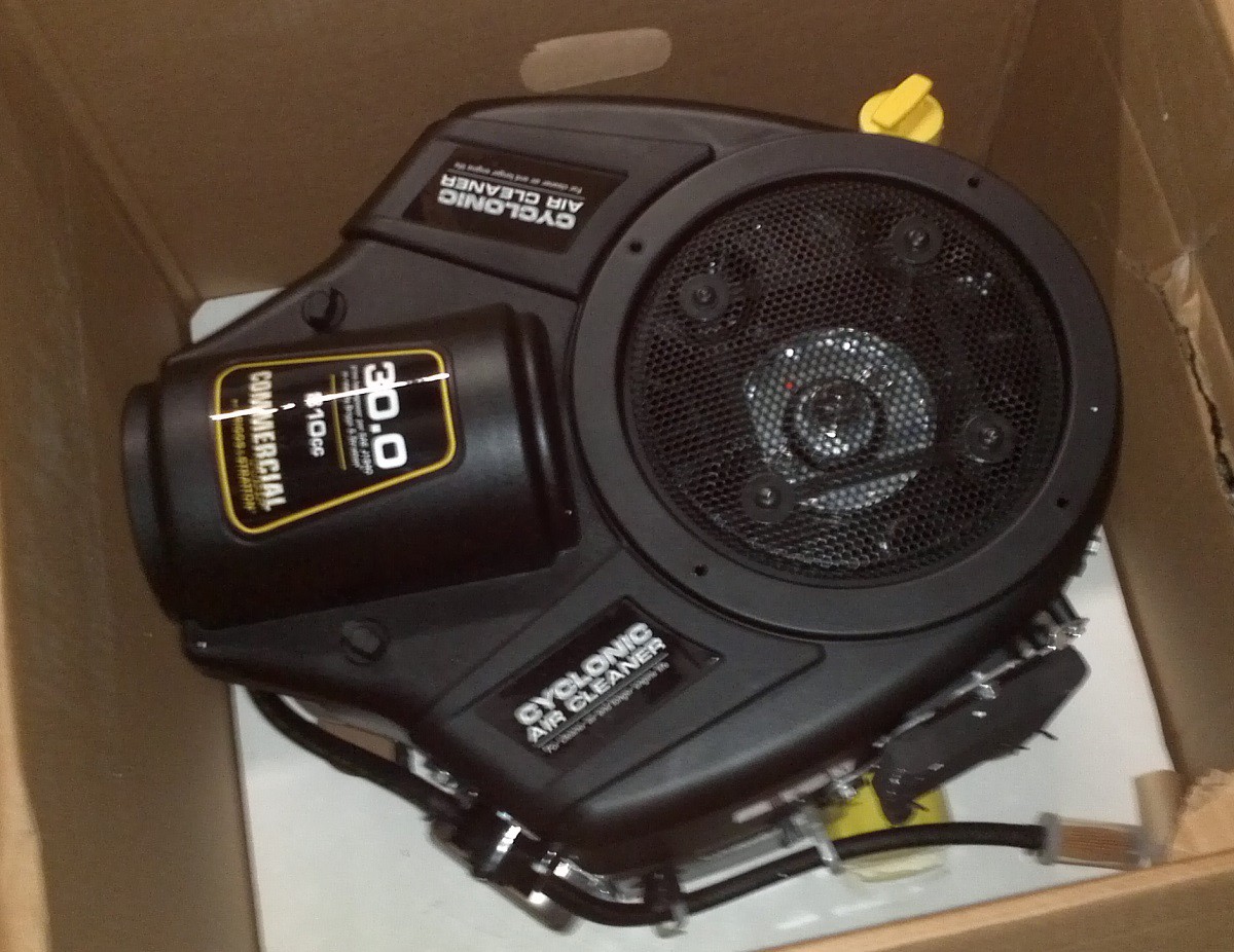
The chosen engine was simply the biggest vertical shaft gas engine I can easily order off the Internet. This ended up being a 810cc 30HP riding lawn mower engine (note: 30 HP is without air filter and exhaust). It comes with an electric starter, and an alternator. Now this engine doesn't have as great as a power to weight ratio as a motorcycle engine (or other engines) of similar size, but it's made to run in the vertical orientation and it doesn't have an integrated transmission/clutch that would make incorporating it into a quadcopter more complicated.
After doing some part selections and creating an initial design in December and January. The engine was ordered and arrived in early February.
The engine documentation leaves something to be desired. It's marketed as a direct replacement and there is no notes on the required fuel, electrical or exhaust connections. The fuel was simple enough since it's labeled on the tubing that it's 1/4" and the exhaust comes with a gasket that could be measured to find the right parts. The electrical took a bit more research. There were three wires on the engine that all come to the harness. Power from the alternator coming off the regulator, the ignition coils and a fuel shutoff solenoid. After doing some searching I came across two electrical diagrams, both with different wire colors and neither matching the wire colors on this particular engine. It was time to remove the top cover and take a look inside.
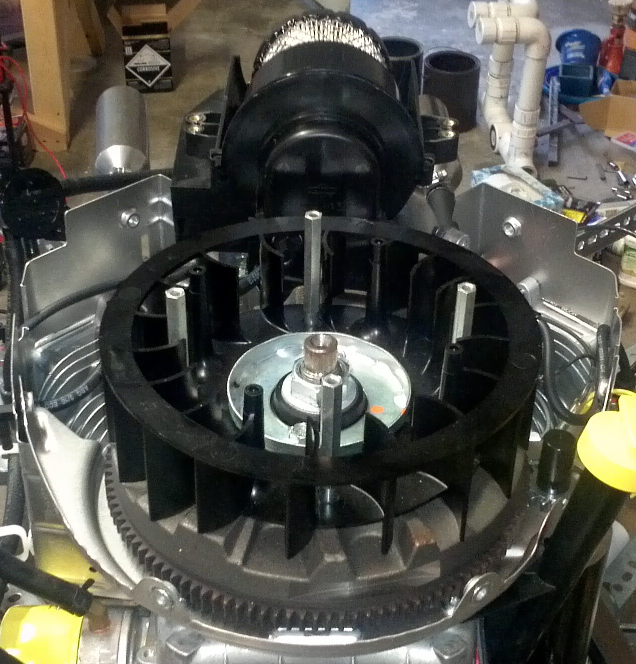
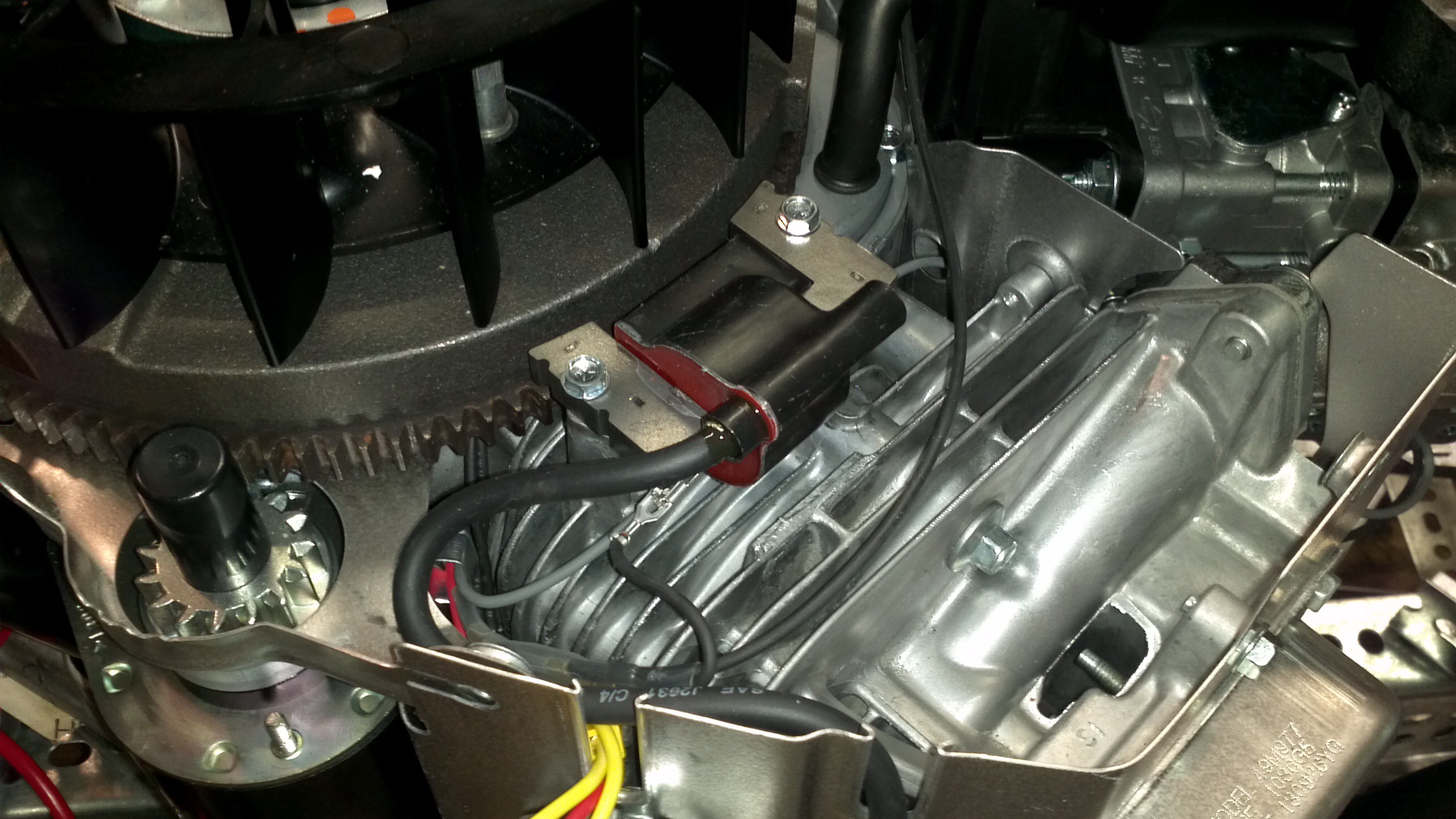
Getting the cover off was a simple process. First the air filter was removed and the oil cooler was unbolted. Next the screen for the engine cooling air was removed and then there was just a few bolts on the cover. Once inside the wires were easy enough to trace back to various parts. Red was the power from the regulator, black was the ignition coils and gray went to the fuel shutoff solenoid. This will be noted on the wiring diagram that will be posted later.
With the engine in hand it was time to start building the frame around it. That'll be covered in a later post.
Discussions
Become a Hackaday.io Member
Create an account to leave a comment. Already have an account? Log In.