 Peter McCloud
Most of this weekend was spent working on the propellers. Goliath was designed with four, two bladed propellers, each three feet in diameter. The were designed using Blade Element Theory for the specific RPM and loading Goliath is expected to experience.
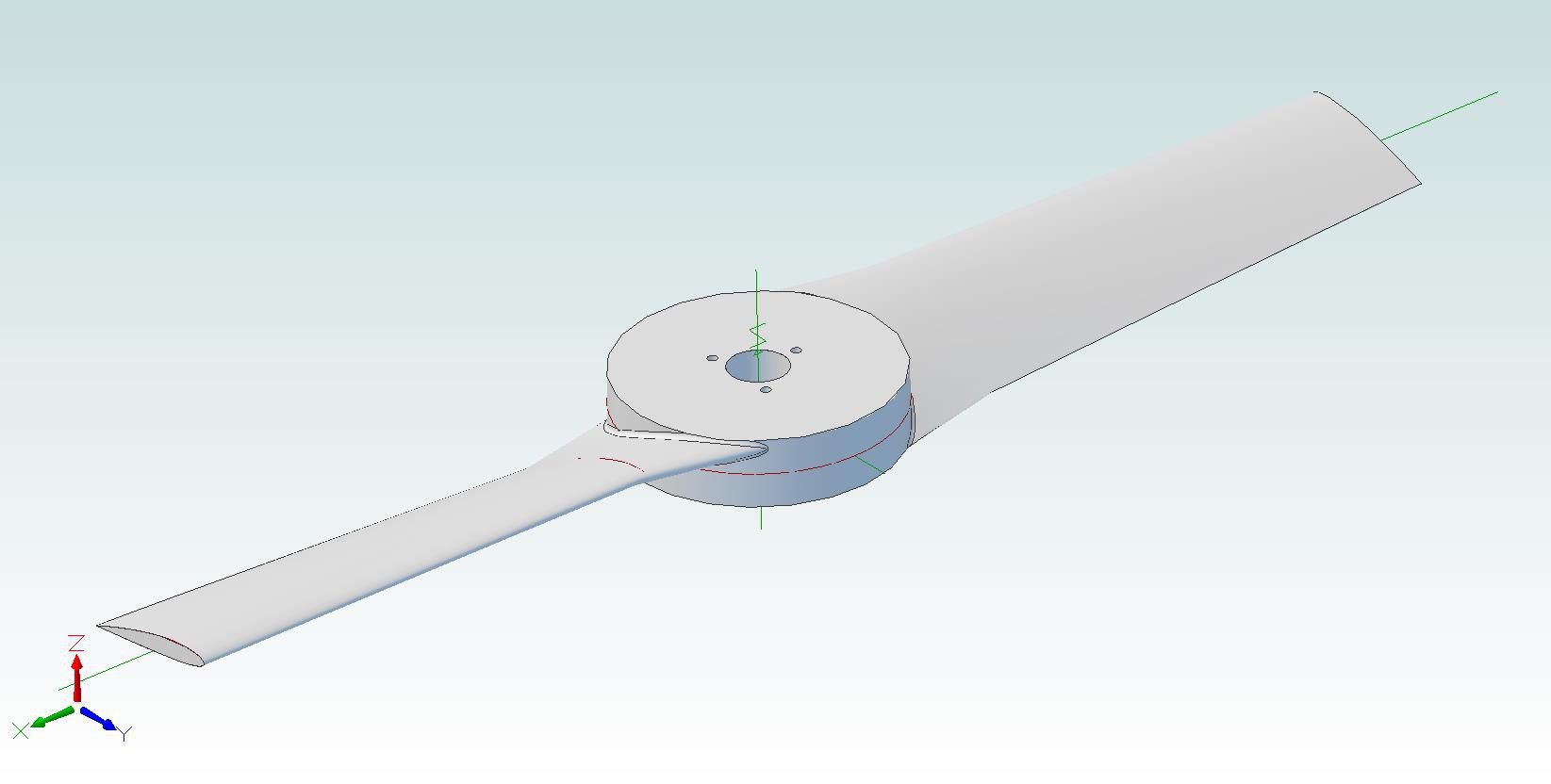
The propellers will be made with foam cores covered with composites. The foam cores are created using a CNC Router which isn't a straight forward process because the part needs to be machined on both sides. To do this, supports are needed to hold the part in place while machining the backside. This could be done using the CAM software, but more detailed supports can be built using the CAD software.
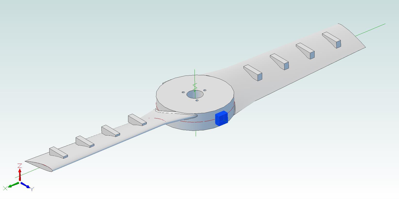
With the supports added, the CAD file was loaded in the CAM software (MeshCAM) and the tool paths were created. With the software side completed, the next step was creating the foam blanks. The foam blanks are made out of styrofoam sheets available at most any hardware store.
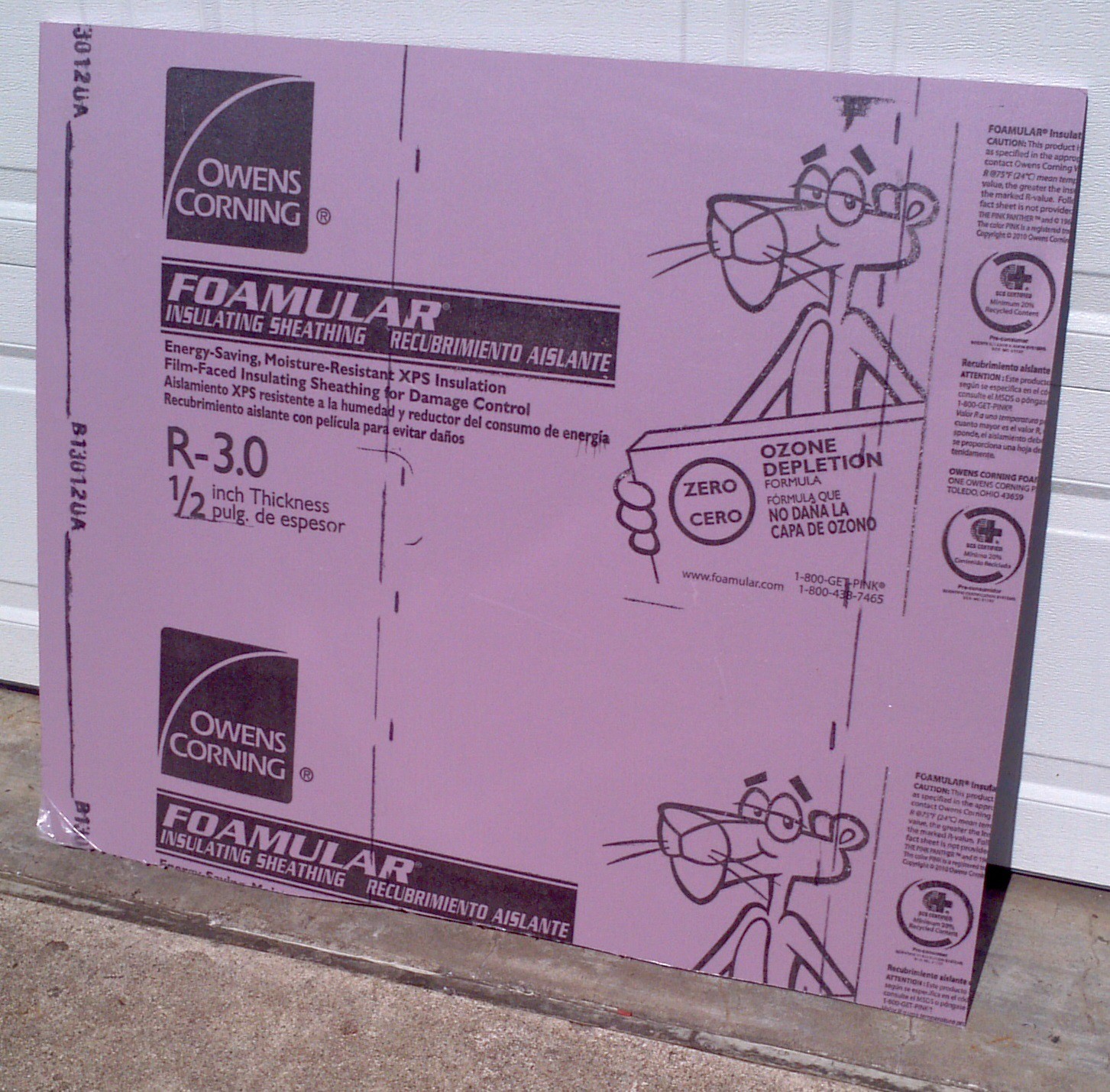
Three 38" x 10" pieces are cut and the protective coating is peeled off of both sides. It's important to do this because the coating doesn't cut well and can get wrapped around the router bits and ruin your part.
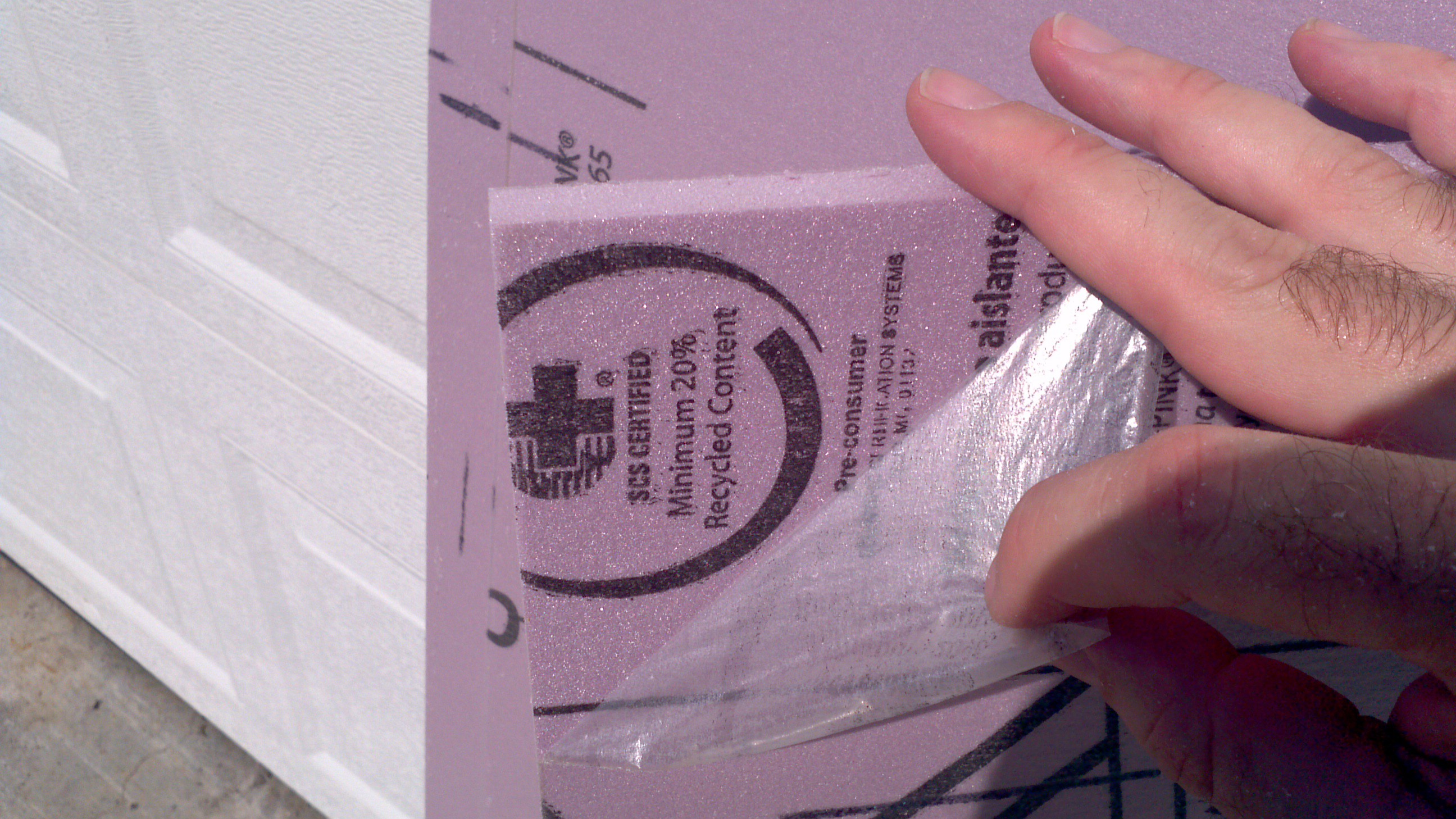
The three sheets are sprayed with adhesive (For this block, Loctite medium hold was used) and glued together to make one larger block. Note the label on the original sheet that says 1/2" thick. These sheets are NOT 1/2" thick. Even with the coating removed, the three sheets have a total height of 1.75". This is the thickness the propeller was designed to. With the block glued together, it was mounted onto the table with 6 wood screws and was ready to cut.
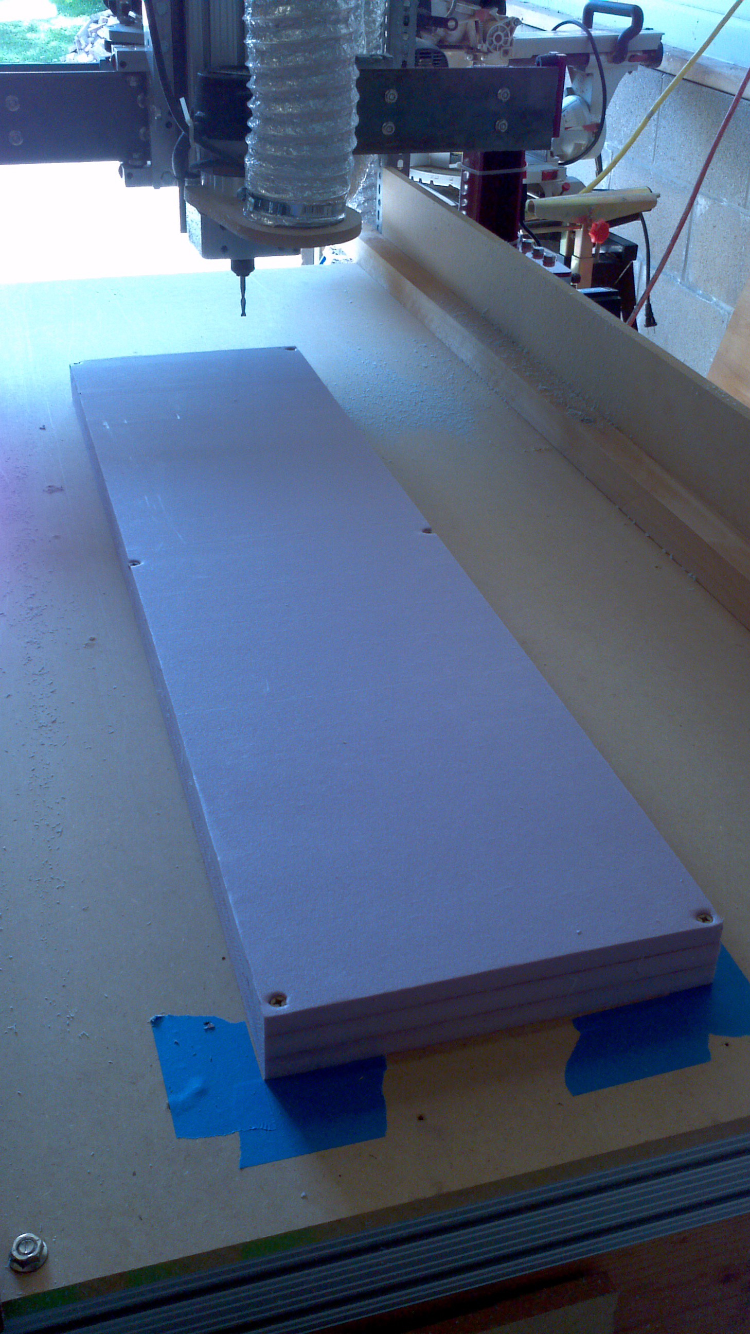
A roughing pass was done using a 1/2" straight bit with 1/4" deep passes. Probably could have been more aggressive since the foam was easy to cut, but the process is still being refined. the results of the roughing is shown below.
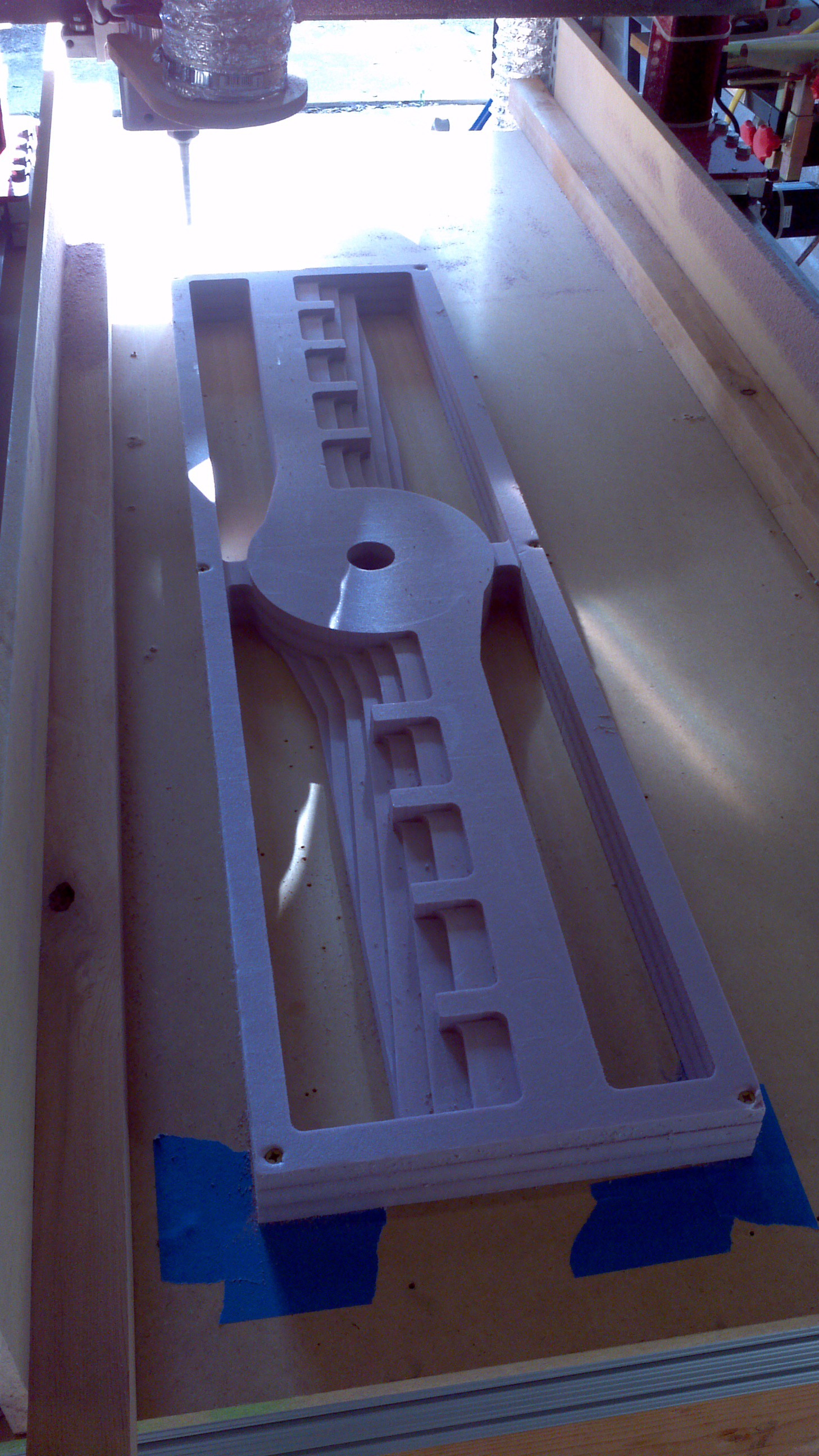
With the roughing complete, a few finishing passes were made. Both an X and Y parallel pass were made and a pencil operation to clean up some of the surfaces. The last operation was to drill the mounting holes and some extra alignment holes at the ends of the propellers. All of this holes will be used to align the part when it's flipped over to machine the other side.
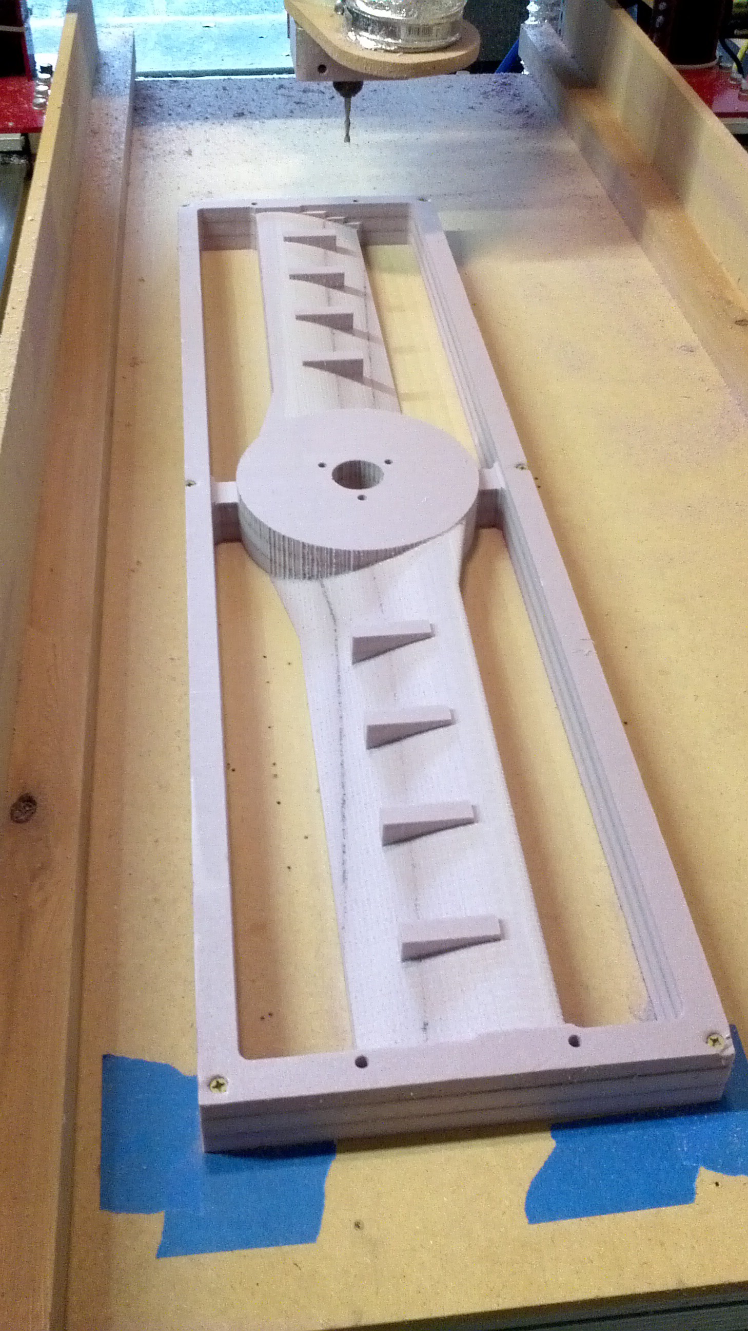
The part was then removed and the alignment holes were drilled into the spoil board. The part was then flipped overand wood dowels were then used to align the part and to help hold it in place.
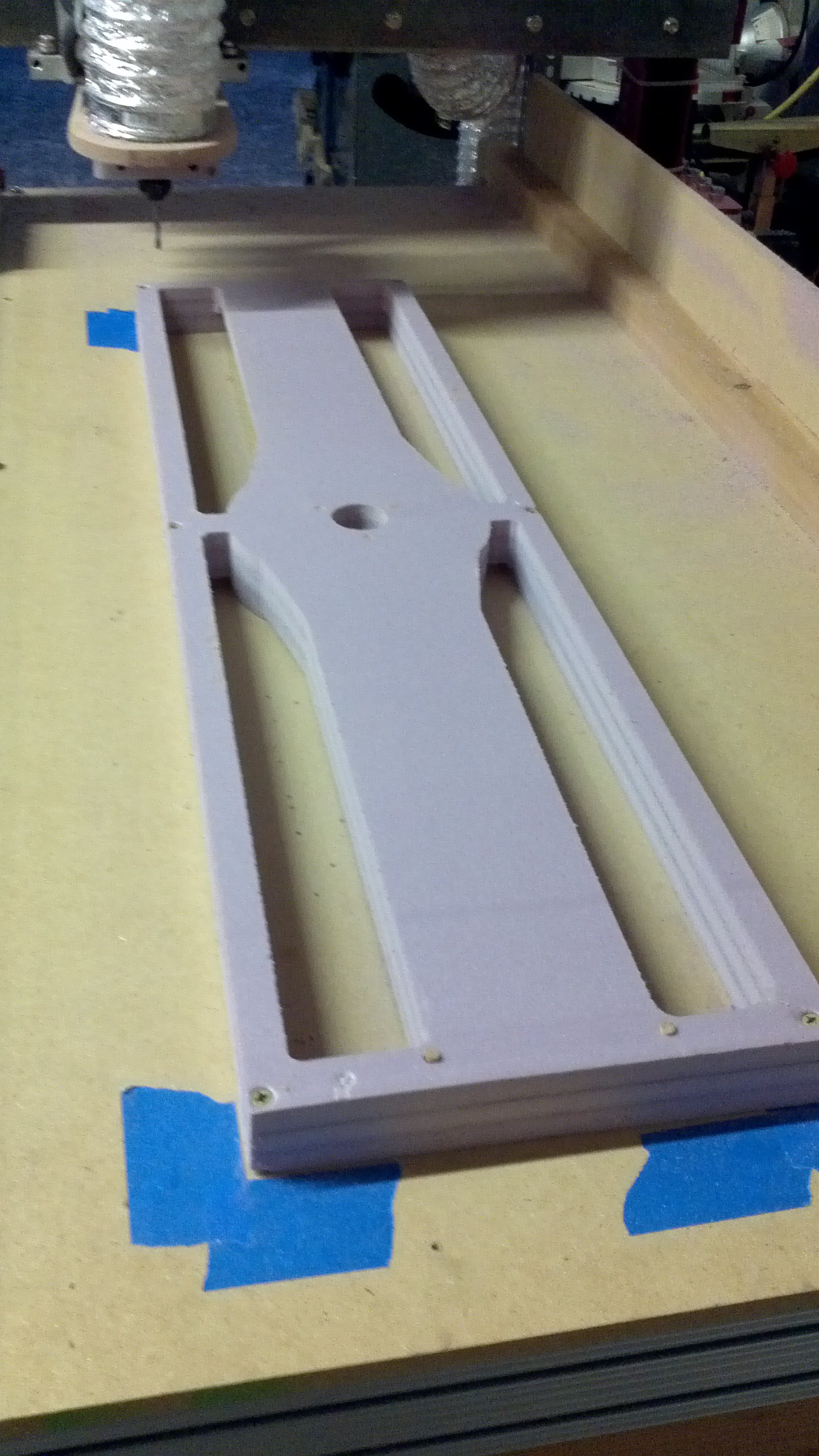
That was all the progress made this weekend. The next steps will be machining the backside and starting the process of adding composite reinforcements to the core.
Discussions
Become a Hackaday.io Member
Create an account to leave a comment. Already have an account? Log In.
Are you sure? yes | no
Are you sure? yes | no