 Peter McCloud
After completing the frame, the next step was building the drive system. Quadcopters traditionally use 4 individual motors with two spinning clockwise and two spinning counter clockwise to balance out the torque. Since Goliath uses a single engine, the drive system not only has to distribute power to each of the props, it also has to balance out the torque.
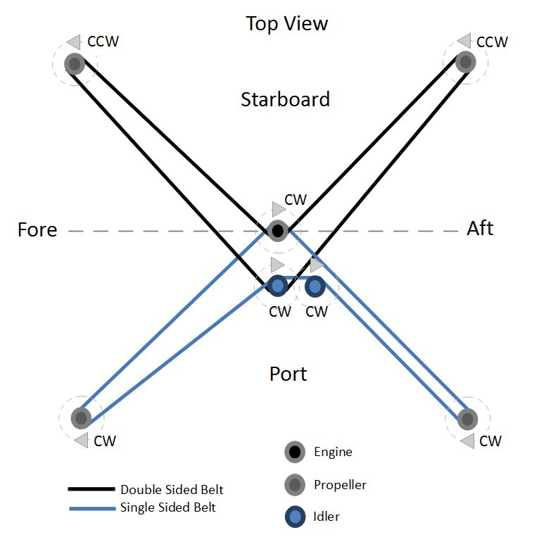
A belt system was chosen early on after considering the horsepower and speed requirements. In particular, the belts are HTD, with an 8mm pitch and 20 mm width. One single sided belt turns two of the propellers in the same direction as the engine and a double sided belt is used to turn the other two propellers in the opposite direction. Two idler pulleys, one for each belt are used to tension the two belts.
The first step in building the drive system was to attach the main pulley to the engine. This is a 50 mm wide pulley directly mounted to the engine shaft with a shaft key. A 50 mm wide pulley was chosen to fit the two 20 mm belts with a 10 mm gap between them.
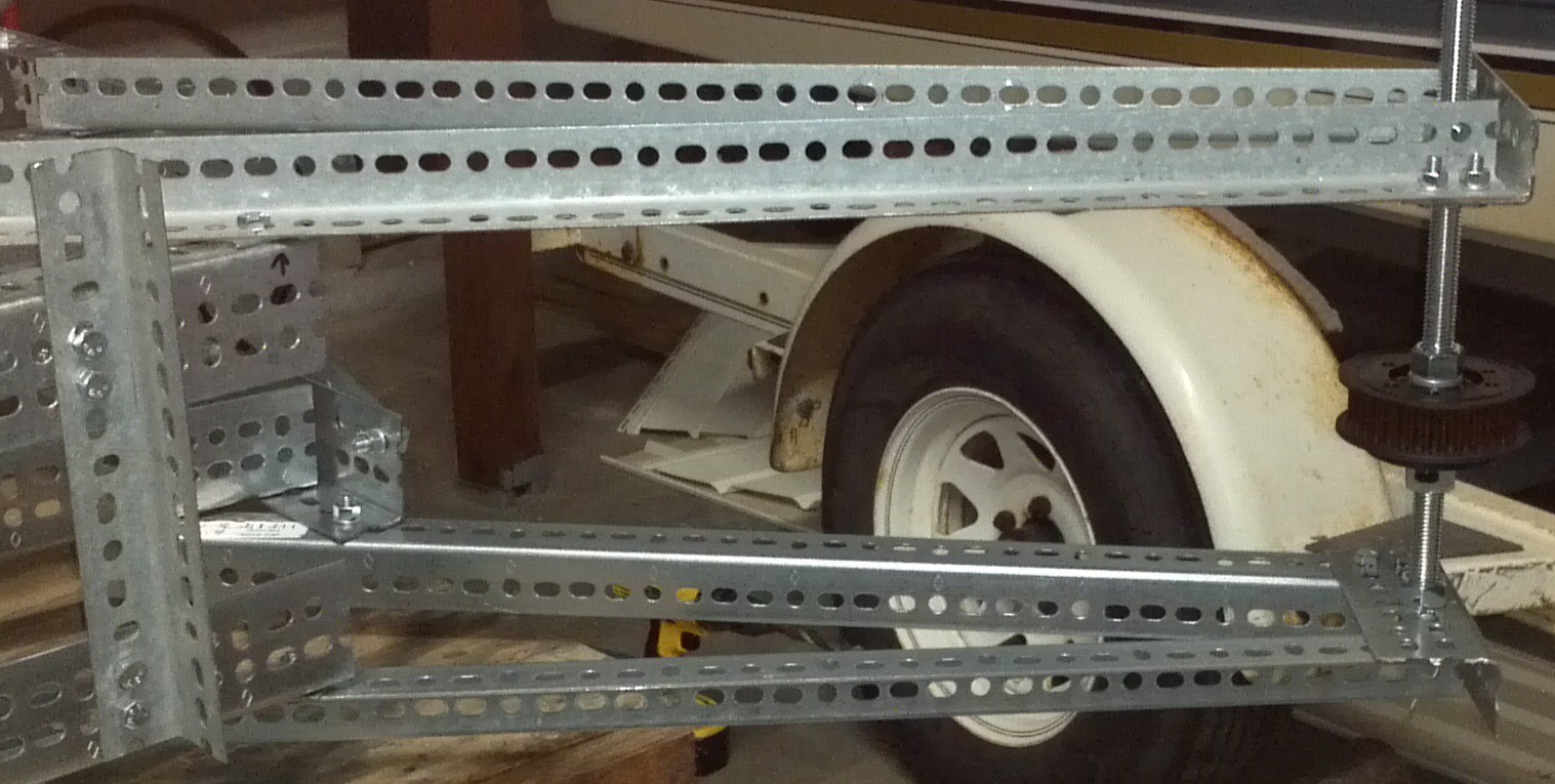
The next step was to assembling the shafts and pulleys for each rotor. The pulleys are mounted to a drive shaft using a ball bearing bushing. The drive shaft is simply 3/4" all thread and is bolted to the upper and lower support arms. Later, each propeller will be bolted to the pulleys.
Once the engine and propeller pulleys were mounted, a piece of string was used to measure the required belt sizes and lay out the location of the idler pulleys.
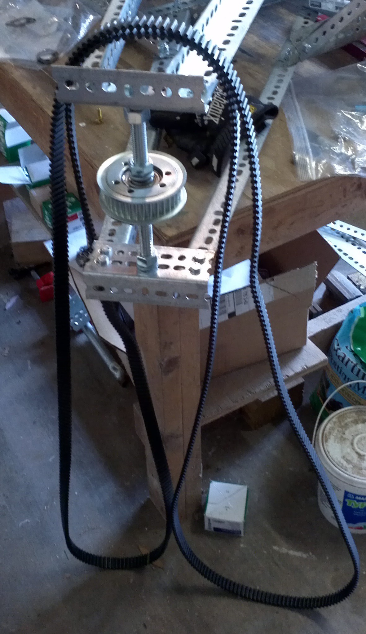
When researching HTD belts, it was surprising to find out how much power they can handle. The strength is due to the continuous length of cord inside the neoprene rubber. The downside to this design is that the belts come in set lengths and splicing them will severely reduce the load the belts can handle. So after measuring the belts, the next biggest size length was selected and the locations of the idlers were chosen to take up the slack. Shown below is the double sided belt.
 The idlers are mounted onto 3/4" square steel tube and rotate about a vertical piece of 3/8" all thread. This allows the pulley to rotate about the all thread and apply tension to the belt.
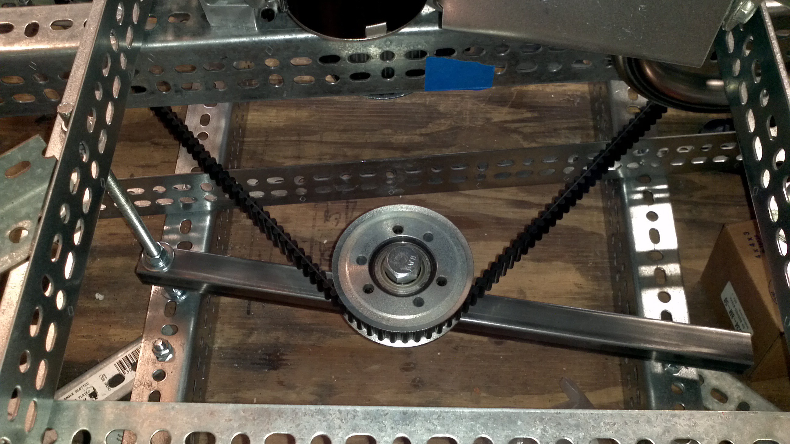
On the opposite side of pulley, another length of all thread is attached horizontally. This piece is used to set the tension.
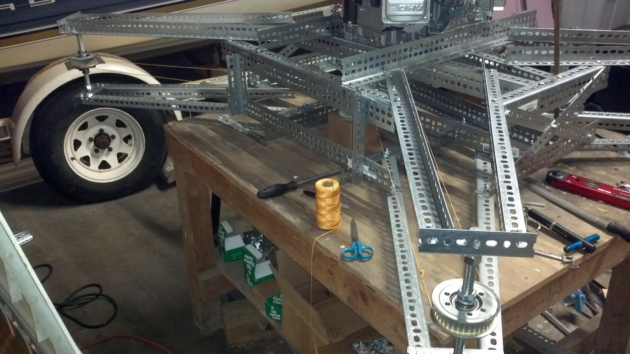
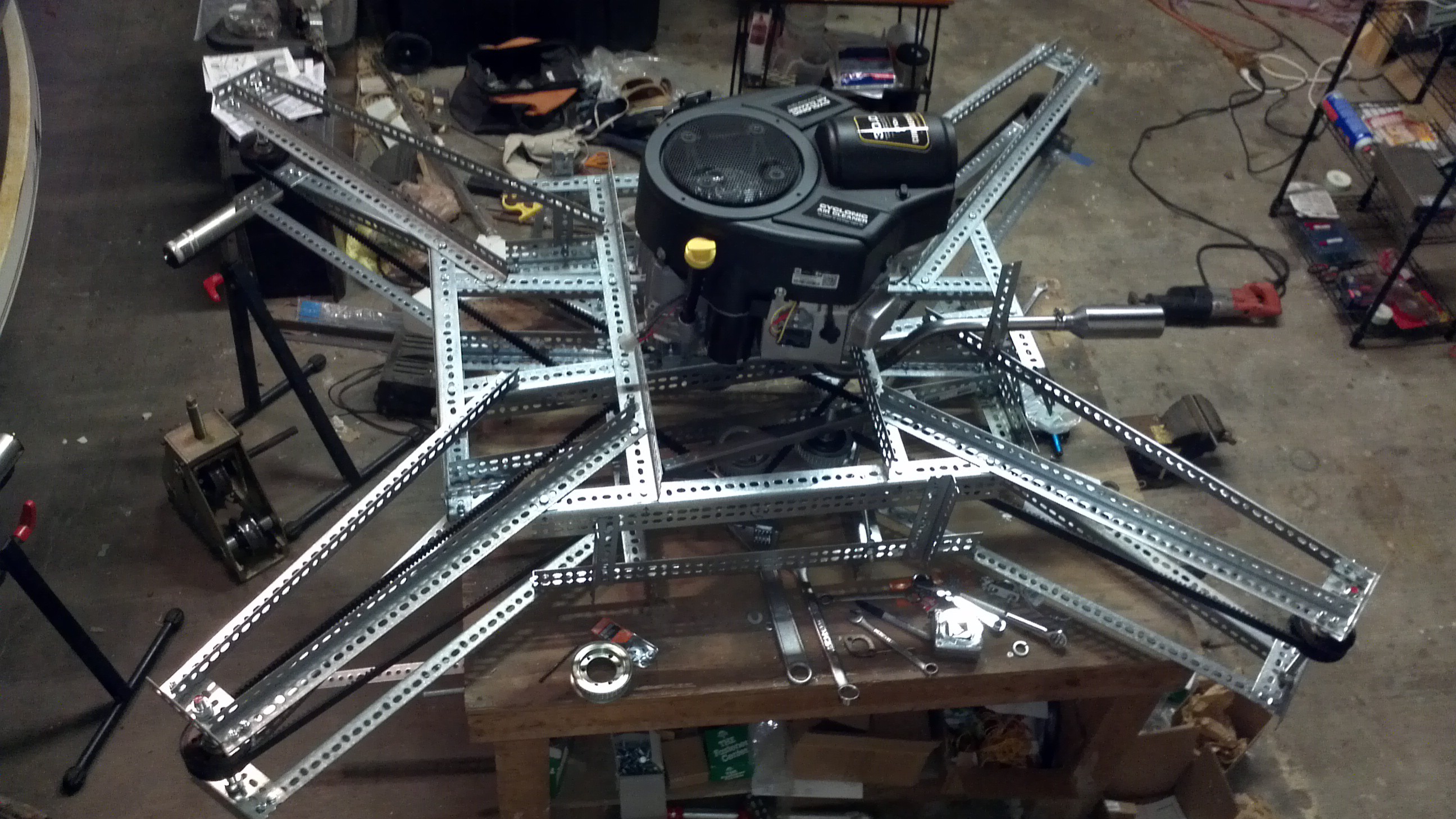
 After assembling the idlers, tightening the belts and the making sure the pulleys were aligned, the drive system was complete! If you look closely, you'll see part of the exhaust system being test fit. We'll cover that in one of the upcoming project logs.
Discussions
Become a Hackaday.io Member
Create an account to leave a comment. Already have an account? Log In.