 Peter McCloud
The engine mounting plate has been completed and the middle portion of the Mk. II frame is now complete.
Designing the engine mounting plate required working though a few iterations before the coming to current design. The plate is made from 1/8" thick 6061-T6 Al plate from Aircraft Spruce. It wasn't cheap, so making sure the design was good before cutting the material was important.
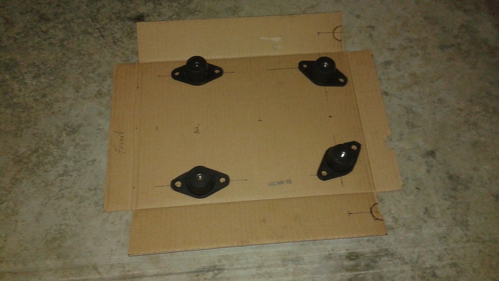
The first step was setting up the initial layout, using cardboard to layout the engine mounts and make sure that the plate wouldn't be in the way of the exhaust. The engine mounts are made of rubber and steel and should help with dampening some of the vibration from the engine.
After doing the cardboard layout, and comparing it to the Mk. I design, it became apparent that it would make sense to go ahead and incorporate the mount one of the idler pulleys as part of the design.
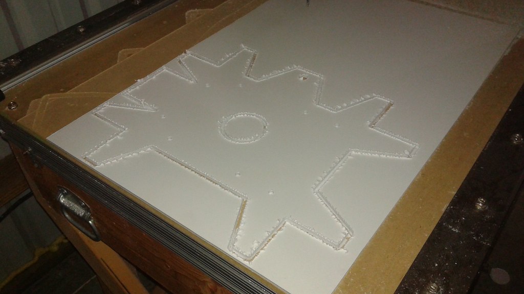
Next, the part was designed using CAD and another prototype was machined using foam board. One other feature incorporated. at this point was multiple tabs on the sides of the plate for attaching to both the lower and upper frames. The tabs would be bent +/- 15 degrees depending on which half of the frame it would be attached to.
 However, after holding the part inside the new frame a very big design flaw become apparent. The middle tabs were meant to be bent downwards, but that would place them in the way of the idler pulley, which will be placed below the engine plate. Second, I could go to both the lower and upper frame from the engine plate directly, otherwise the structure would have to pass through the belts. If that was done I'd have to assemble and re-assemble the frame every time the belts were added or removed.
It was decided to just attached the engine plate to the upper frame, similar to how the Mk I frame is laid out. The plate was redesigned. one last time, this time adding engine mounts to the front and back and also adding a mounting area for the motor servos at the aft end of the plate.
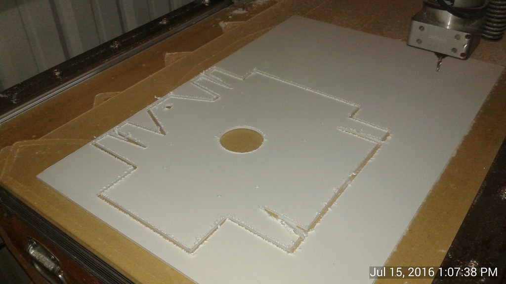
 After a test fit, the design was complete and the part was ready to be machined using the aluminum plate. Since the CNC router needs to go slow to cut the aluminum plate, it took about an hour to cut the part. In the images, the edges of the plate look somewhat rough. This is actually the protective film that is on both sides of the plate. The actual edges come out very clean.
 After cutting, the tabs were bent to the correct angles using the press brake. The protective film has been left on to prevent marring the material.
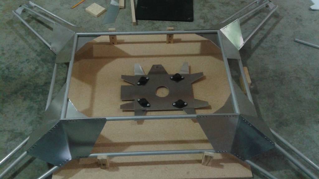
 After getting all of the bends to the right angle, the mounts were placed on the plate and the engine was test fit to make sure all of the clearances looked good.
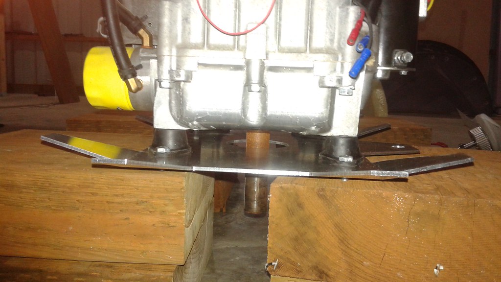
With the engine plate complete, it was time to start attaching it to the upper frame. I'll have those details in the next log.
Discussions
Become a Hackaday.io Member
Create an account to leave a comment. Already have an account? Log In.