 David H Haffner Sr
Well, using my homemade laser collimation tube assembly and a glass cuvette filled with 99.9% pure Isopropyl alcohol, I shot a <5mW laser thru it to get an idea of my spectrometer's real resolving power and here are the results;
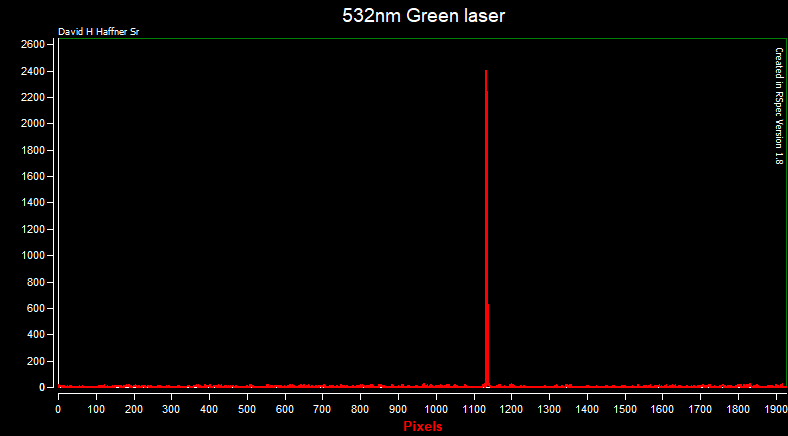
This is the raw data captured from RSpec;
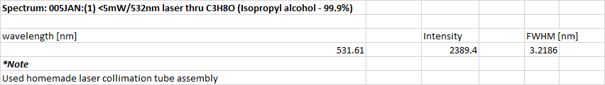
This is the FWHM data;
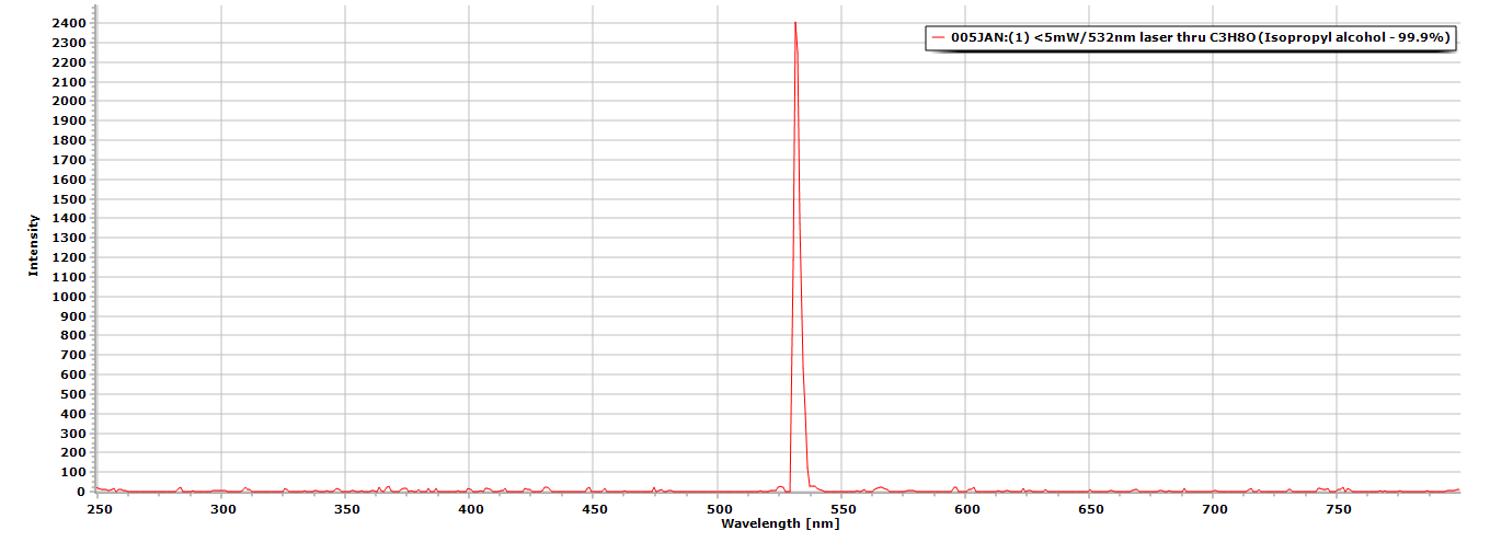
This is the calibrated spectrum;
Discussions
Become a Hackaday.io Member
Create an account to leave a comment. Already have an account? Log In.
I'm impressed!
Are you sure? yes | no
Thank you Thomas :)
Are you sure? yes | no
I would have expected artifacts from surface reflection, or scattered light but none of that is visible in the raw data plot.
In the past I did projected fringes 3D measurement with CCDs exploiting the distribution of optical sensitivity of the metalization. Line sensors are, of course less likely to create pronounce masking effects but everything that falls within the sensitive area of a pixels loses some lateral information (that's akin to sampling artifacts in the time domain), and I expect some Nyquist criterion violation to happen. Did you make an estimation of that error?
Are you sure? yes | no
Well Thomas, several factors are in play here, lots of filters! 1 Schott glass longpass filter close to the detector eliminates quite a lot of PLA effects. 2, very painstaking alignments, and I mean "painstaking!" The biggest one is getting the beam, whether broadband or laser, at dead center of the 1st dicrotic collimation mirror, or all bets are off, same goes for the laser collimation tube, which has a Sapphire window @ 45 deg in order to keep the beam parallel to the achromatic coated 18mm doublet focusing lens.
3rd, lots of special blackout tape, kind of like a felt-like material designed for applications just like this, 100% NO reflectivity. 4th, RSpec is pretty sophisticated in that, it lets me bin up to 6 frames a second and average up to 100 frames a second, and also control negative flux.
So there are a lot of factors going on behind the scenes, but I always like to present the raw data both in RSpec and in CSV format just to keep the scientific process on the up and up :) Opps, almost forgot another filter, the 1 for the laser collimation tube assembly, its a 532nm bandpass filter (Thorlabs) same with the Schott glass filter, expensive but worth the investment :)
Are you sure? yes | no
That's pretty sophisticated. I've been following your project for some time - you're now clearly at expert level. Most likely you could build other optical instruments with that knowledge.
Are you sure? yes | no
Yeah, 3 years I guess taught me a thing or 2 :)
Are you sure? yes | no
I'm impressed.
How wide do you think the line is in reality?
If the laser bandwidth is really tiny, then you are measuring the impulse response of your spectrometer (at one frequency, anyway). If you assume you have that same response across the spectrum, you could deconvolve measured spectra using this response to improve the resolution.
For all I know, your software already does this.
Are you sure? yes | no
Hey Ted, actually this is the bandwidth formula that you use to calculate this;
1 X slit width X diffraction grating mm/gr = BP
R = wavelength/BP
= resolution
So, we take the 1st part of the formula; 1 X 0.1 X 1540 = 154
R = 532/154
R = 3.45nm
That is our theoretical resolved power, that's why it was critical for me to actually calibrate the laser line to get it's "true" FWHM value which was 531.61nm, which using the formula above gives me my resolution of 3.2nm
Still not perfect, I would have still had to calculate a Guassian distribution probability curve but the formula above is still very valid.
Also I'm handicapped by the fact that I'm using a DVD piece as my diffraction grating and a cmos camera, but this setup is giving me an idea how to fix some major problems with the 8-bit CCD circuit.
Are you sure? yes | no