 peter jansen
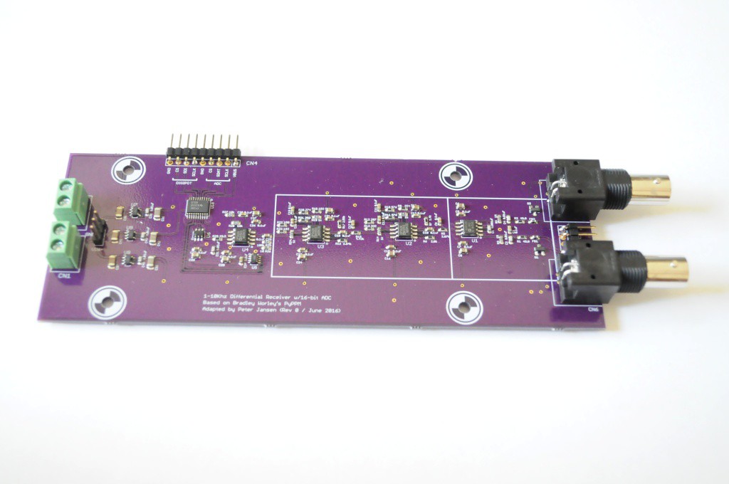
A quick update, with the first pass at a proton precession amplifier!
When I'd placed this project on the backburner last year, it was after hitting two technical challenges that I didn't have good solutions for:
- Assembling quality radio coils (which can now be done largely automatically using the handy coil winder!)
- An inexpensive, tractable way of amplifying, sampling, and digitizing the very low amplitude proton precession signal over a broad range of frequencies.
This second bit is addressed by the amplifier board, described in this post.
I'd realized that most of my issues in coming up with a design for the amplifier / analog-to-digital converter were over-estimating the specifications for the board -- too high a sample frequency, resolution, and so forth, and that for a first-pass proof of concept, something with more modest specifications would likely meet with success. Thankfully, the requirements of this design are very similar to an Earth's field Proton Precession Magnetometer, which has a small but non-zero community of open-source builders. Bradley Worley, a graduate student in nuclear magnetic resonance, put together a very well documented and iterated proton precession magnetometer about two years ago, after heavily researching what other's had done -- and his work is a great resource, and the most recent build that I've found.

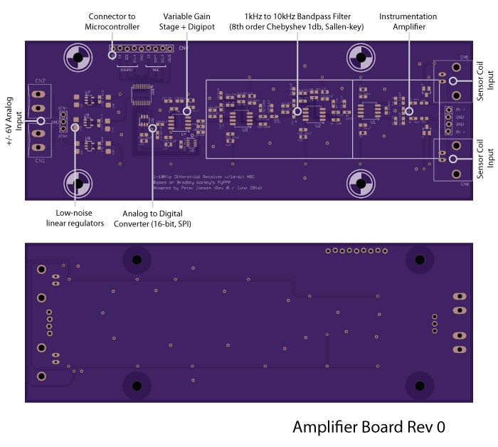
The design I've put together is heavily based on Bradley's design, and uses the same ultra-low noise instrumentation amplifier, low-noise filter opamps, and 16-bit SPI ADC. I'm still a novice at many things analog, including low-noise design, and took the opportunity to pored over the Analog Devices application notes to understand the design choices that were made, and where they might be improved. I made a few modifications to the original design:
- The signal chain now progresses as: instrumentation amplifier -> bandpass filter -> additional gain -> adc. In the original design, the gain was all completed before the bandpass filter, but this this could allow the noise to clip the signal before it's filtered.
- Instrumentation amplifier: The internal bandpass filter was lowered. I changed the topology of the input protection diodes to the "low noise" topology in an Analog application note.
- Bandpass filter: I couldn't find the original specifications for this, and PPMs are intended for Earth's field, so they can get by with a much narrower frequency range. Here, the bandpass filter has a 1-10kHz bandpass window, and uses the Sallen-key topology, which looks to have better noise characteristics than the original Multiple feedback topology.
- Second gain stage: Since I don't have a good idea of what the signal intensity will be, and it'll likely be variable depending on the sample size, I've modified the second-stage gain to be variable. This is controlled through the AD5160 digipot, which I had success with in the OpenCT2 radiation detectors.
- ADC: The same AD7680 16-bit 100ksps SPI ADC is used. Instead of having an onboard microcontroller, I've broken out the input to the ADC and digipot to a header, so that I can first try interfacing to a Raspberry Pi, which has plenty of buffer memory, and fall back to using another system if that ends up generating too much noise.
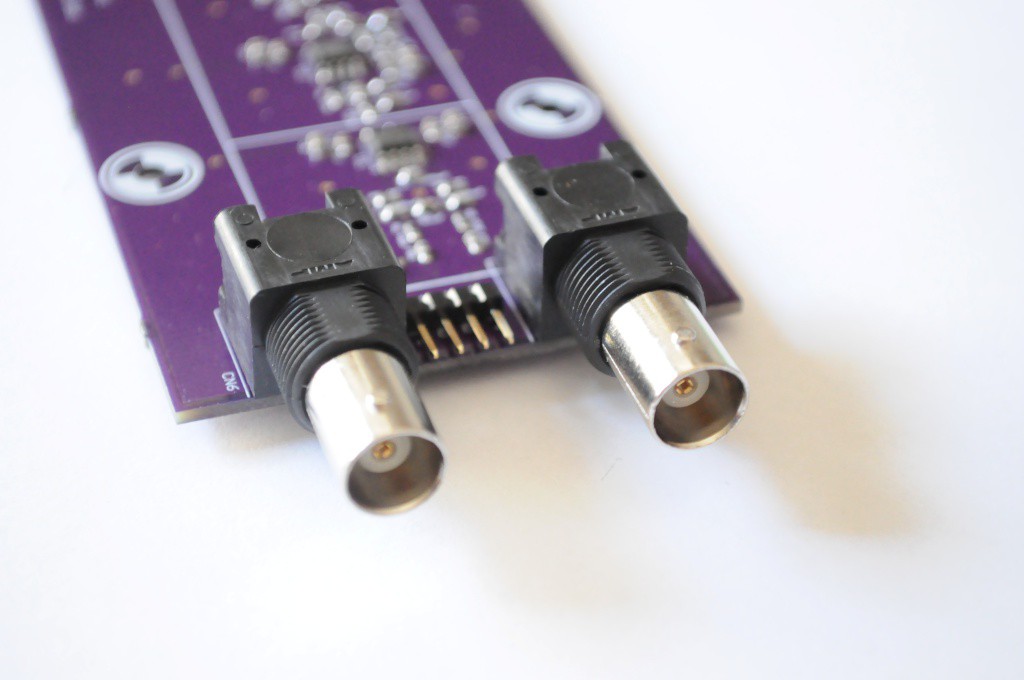
The input to the instrumentation amplifier is differential, allowing for a humbucker coil to be used, as Bradley spec'd for the PyPPM, and the folks who wrote Signals from the Subatomic World used.
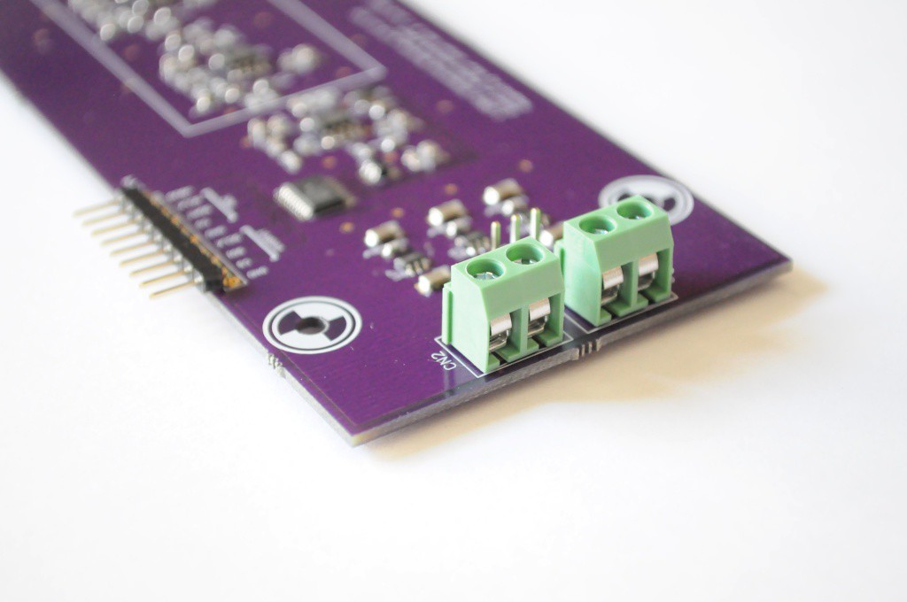
The amplifiers require dual supplies, which are regulated to +/-5V. I think two 9V batteries should work famously -- the draw is very low.
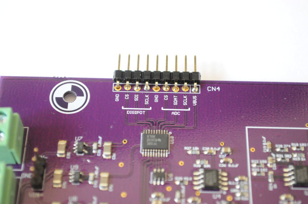
And the user interface connection, with separate SPI pins for both the digipot and the ADC. Here I've opted to break out each SPI interface individually rather than share the clock and data lines as the digipot will likely rarely be changed, but is part of the final gain stage -- so I wanted to avoid having a trace carrying the ~2MHz SPI clock for the ADC nearby, potentially introducing noise.
Next steps
The board powers and passed the "smoke test" (didn't catch fire when I applied power, always a good sign). The next step is to connect the sensor coil and a microcontroller, and sample data (which will all be noise), to verify the design. This board also doesn't include any aspect of the polarizing magnetic field coil driver, which is largely a relay and a constant-current driver, and that should be the last critical bit to attempting to observe a proton precession signal -- the first step towards imaging.
Thanks for reading!
Discussions
Become a Hackaday.io Member
Create an account to leave a comment. Already have an account? Log In.