 peter jansen
A quick update, with some progress on the magnetic-field-measuring-jig!
Figuring out a way to measure the magnetic fields inside of the magnet bore has been something I've been thinking and prototyping for a while now. In this case, the task is complicated by:
- The need for anything magnetic (and, metal in general) to be some distance away from the magnet coil, sensor coil, and magnetometer. The working distance I've been using when sketching the prototype is somewhere between a 15-20cm minimum.
- The potential need for the entire system to need to be tilted on an angle to maximize the difference in direction between Earth's field and the prepolarizing field.
These unusual requirements have led me through a bunch of unusual design choices and prototypes, from 64-magnetometer imaging arrays to a polar cylindrical cnc system for measuring magnetic fields that I put together last year, that included (among other things) dental floss and elastic bands as the main source of non-metalic, non-magnetic drive components for one of the axes. I think part of the reason why I've made these choices, aside from it being a strange problem, is that I really like to explore how to design and make inexpensive, easily-sourced mechanical systems with rapid prototyping systems like laser cutters. But -- forest for the trees -- as enjoyable as it is to design these, at some point you have to pick a design, and work the rest of the problem.
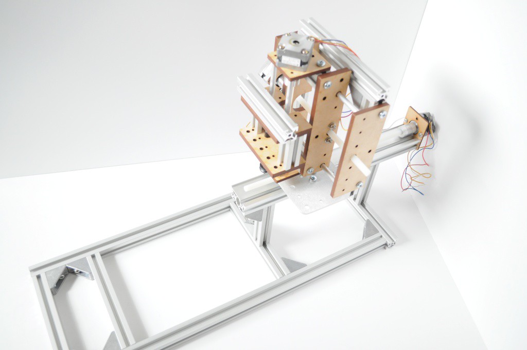
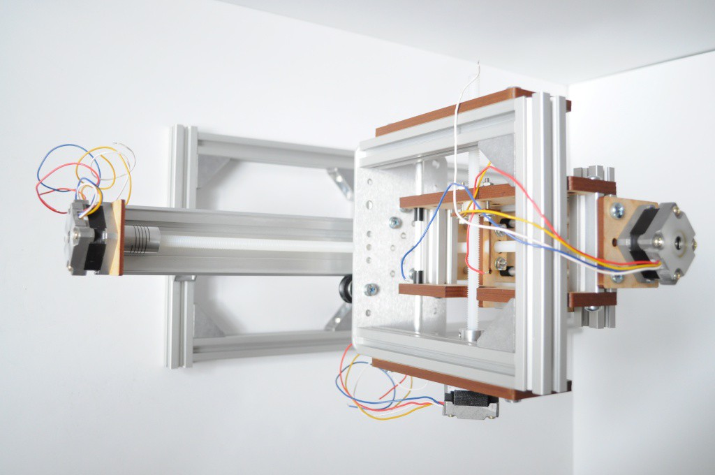
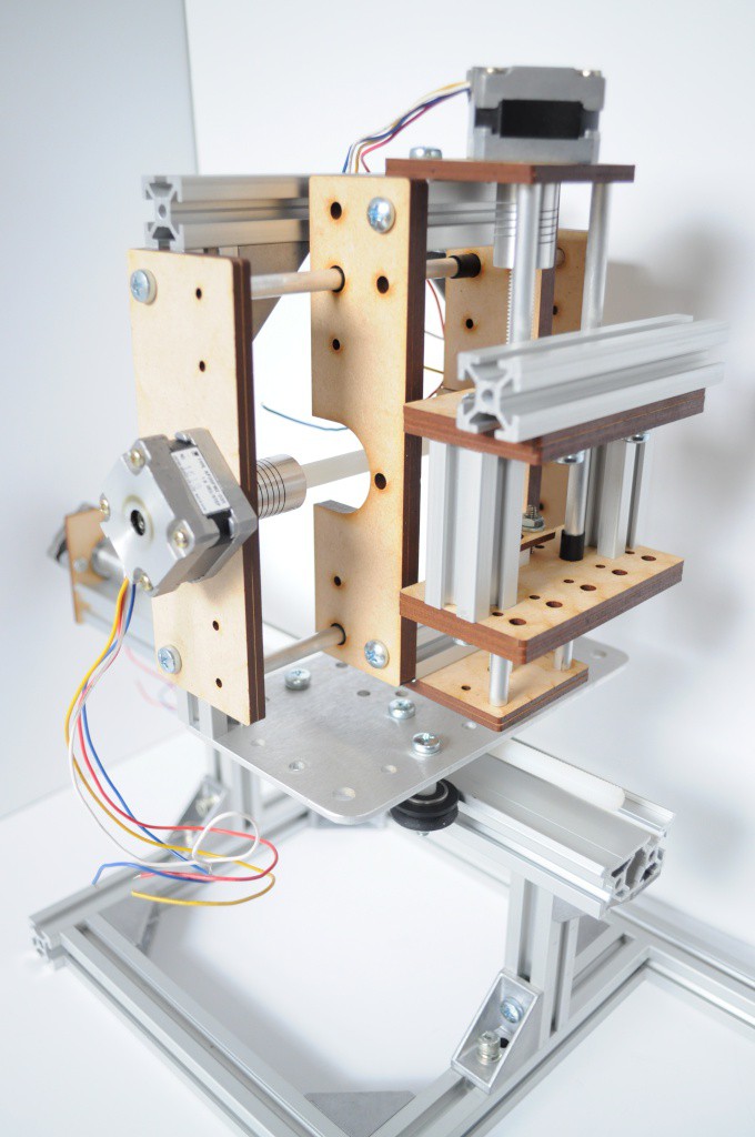
With the design I've settled on, I've tried to keep things as simple as possible given the unusual design requirements. The system is essentially an X/Y table turned on its side, then mounted to a long Z stage. The whole thing is then layed down, and bolted to a supporting frame, that will also include the control electronics for the entire system, as well as the magnet. The magnetometer will mount, so the idea goes, to the outermost axis on the table, on a long stick about a foot or two in length -- as long as possible, while still having the full travel of the bore, plus an inch or two outside to "park" the magnetometer when it's not being used.
Rigidity, repeatability, simplicity and the ability to mount the entire system on one frame drove most of these requirements. All those attempts at an elegant solution -- imaging arrays, polar systems, and in the end it's a magnetometer... mounted on a long stick. Definitely have to laugh at that...
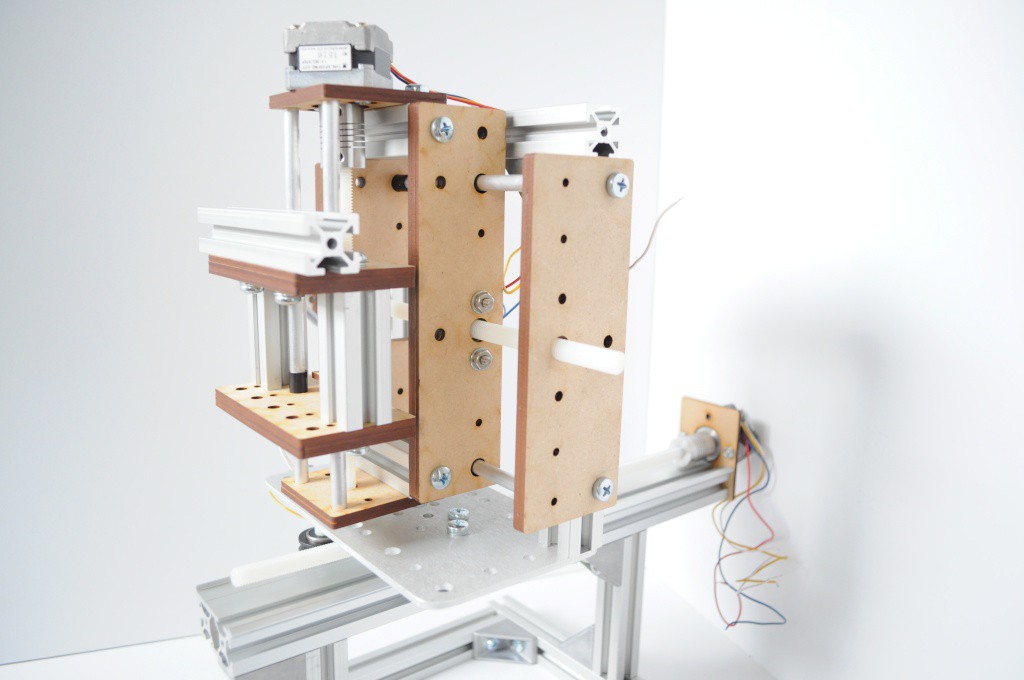
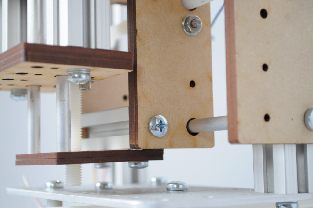
I'm very happy with how these linear axes turned out. The carriages are three pieces of laser-cut MDF, with a cuts that sandwhich 1/4 inch diameter nylon flange bushings firmly in place. The aluminum shafts are 1/4 inch, with what looks to be about a 1-2mm wall. Normally when laser cutting linear axes, I make the entire system out of MDF, but here I decided to add in some pieces of Misumi t-slot aluminum extrusion to increase the rigidity, and make mounting the steppers (and whatever else may need to be mounted) a little easier.
The major partslist for each axis is very minimal:
- NEMA 14 stepper -- I purchased these from a local electronics shop for about $4
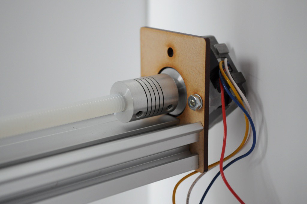
- 5mm to 8mm aluminum shaft coupler -- eBay, about $2 each
- 8mm nylon threaded rod -- $10/meter from McMaster. Each axis uses about $2 worth.
- 1/4 inch aluminum rods -- a few dollars from a local hardware store
- Nylon flange bushing -- four of these are about $1 from the same hardware store
- Misumi extrusion -- cut down from larger pieces, likely a few dollars worth
- Laser cut MDF -- about $1 (assuming access to a laser cutter)
- A handful of M5 screws
This places the mechanical bits in about the ~$10-$15 range, which is very reasonable for a short-travel axis that doesn't require a huge amount of precision.
The "Z" axis is simply a single piece that mounts to the end of a piece of Makerslide, and was reused from the coil winder I cobbled together earlier.
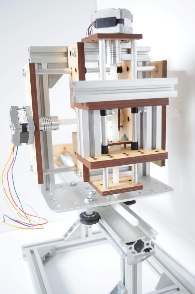
Another vie of the X/Y table. The larger frame is also made of aluminium extrusion, and mounts edge-on to a standard Makerslide carriage plate on the Z axis.
Each of the table axes has about 3-4 inches of linear travel, which is more than the 2 inch diameter of the sensor coil. If this works, I'd like to wind another coil with a larger diameter, to fit larger objects inside.
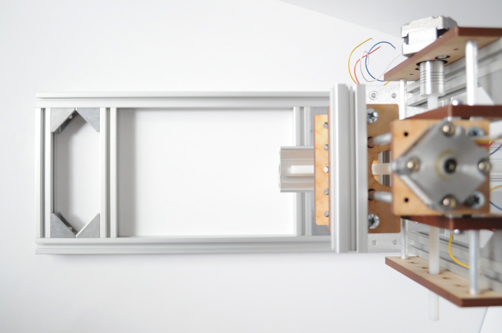
The front end of the system. On the left, a large fork will mount that holds the magnet bore and sensor coil about 20cm high -- both away from the aluminum frame, and high enough that a magnetometer mounted to the outermost table axis on a long stick will be able to travel around the bore without issue.
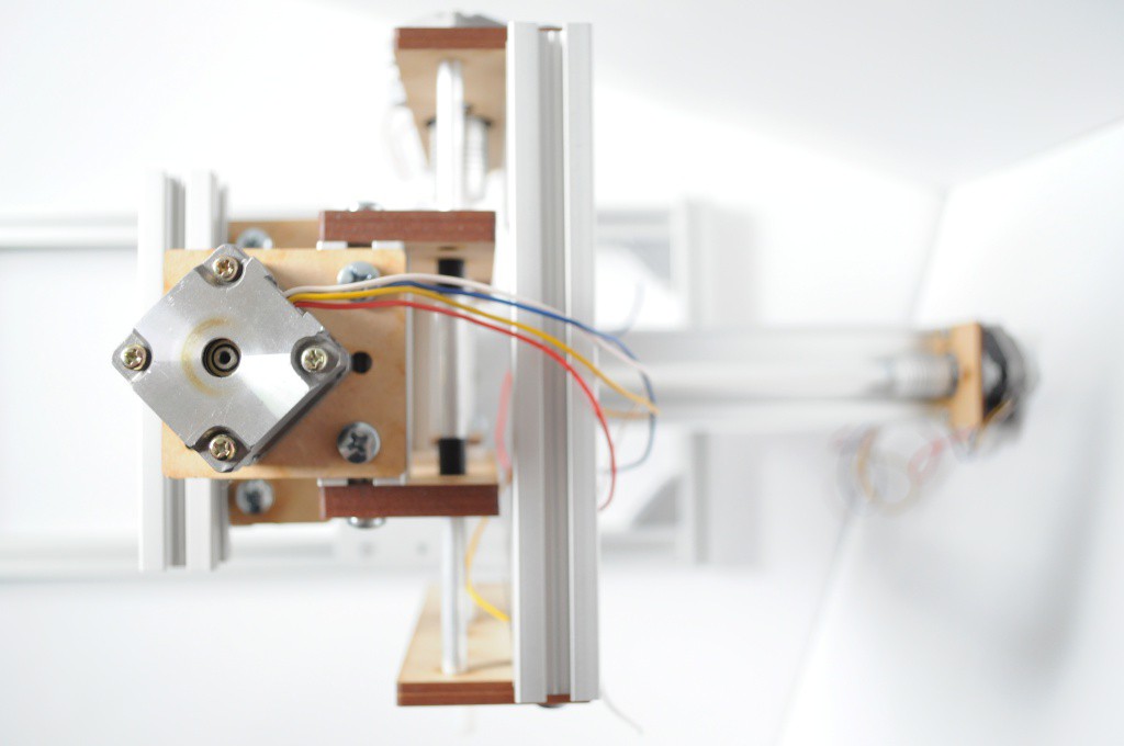
And the back end of the system -- the Z axis. The control electronics will likely mount against the bottom frame toward this end, away from the sensor coil.
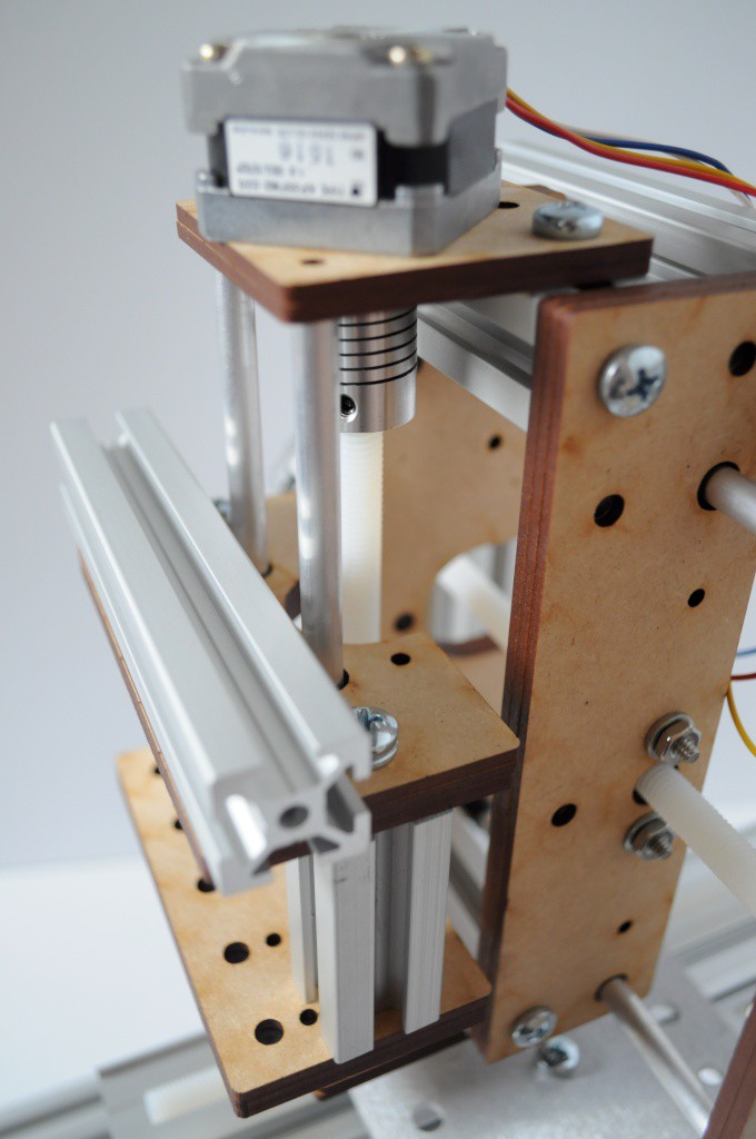
The back/bottom of the table axis is visible here, showing several of the black nylon flange bushings extending along the axis. A cutout is also visible in each axes carriage that lets it slide overtop of the aluminum coupler off each stepper, adding nearly an inch to the travel. This wouldn't normally be a big deal, but with such small axes, this adds an appreciable amount to give them their total of 3-4 inches of travel.
Another view from the "front" of the table, with the notch for the shaft coupler clearly visible.
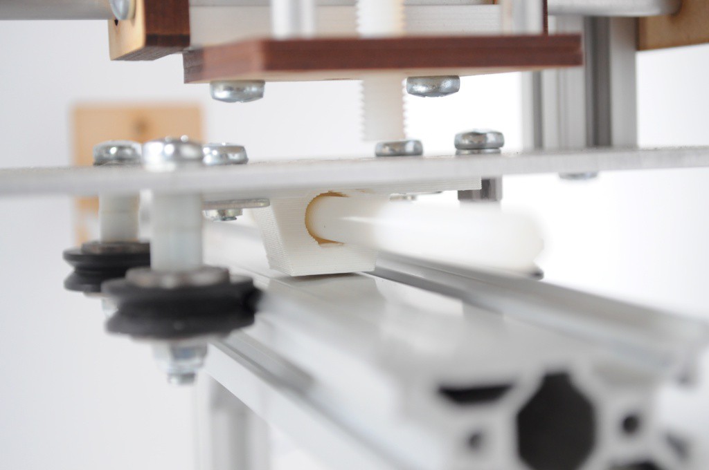
The Z axis transfers motion to the Makerslide carriage through a 3D printed nut holder that mounts to the back of the Makerslide carriage. I designed these for the OpenCT2 project, and they've become very handy for making quick linear axes with Makerslide -- an hour of printing, a quick laser-cut mount plate on the end of the makerslide, and you're often set. This same style of linear axis was also used for the coil winder, though the nut holder was mounted to the top of the Makerslide carriage -- here that wasn't possible, given that the table has lots of things in the way on the top.
A good amount of progress, but plenty left to do. I keep telling myself that I'll get the mount plates for the electronics complete, but the linear axes took a little longer than I had expected to put together. I'm a little slow on a milling machine, so it took me a while to cut down all that aluminum extrusion for this jig and the axes -- but I think it's coming along really well, and I'm excited to see how it works out.
Thanks for reading!
Discussions
Become a Hackaday.io Member
Create an account to leave a comment. Already have an account? Log In.
That looks like an interesting design; sounds like it's going to be just the thing for the range of scanning that you require.
It's not the first mechanism you've posted, either - and they all seem well thought-out. What is your design process for these things? Do you do a comprehensive design in a CAD package, or pencil-and-paper things, or cut-and-try, or a little of each?
Are you sure? yes | no
I usually have some concept that I'd like to try, then I make a quick sketch or two on paper, then draw the designs in Illustrator and cut out a first pass, then iterate as required. For this one, I started with the structure and Z axis, stared at it with a ruler in hand until a design for the lower table axis presented itself, then stared at the lower axis until the upper axis came to mind. My creative process seems much closer to iterative sculpting than it does coming up with a comprehensive design in a CAD package, and I have a great respect for folks who create beautiful structural models in packages like SolidWorks. One day I'll learn.
Are you sure? yes | no