 Krunal
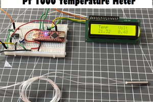
This project needs to be monitor two temperature sensors and one pressure transmitter.
The maximum temperature can go upto 600°C. So I have two options, thermocouple or Platinum RTDs. Since the project estimated life is 20years, and for the external whether conditions, I choose PT100. Also PT100 is proven to be industrial standard.
I started working on interfacing PT100.
The relationship between temperature and resistance is approximately linear over a small temperature range: for example, if you assume that it is linear over the 0 to 100 °C range, the error at 50 °C is 0.4 °C. For precision measurement, it is necessary to linearise the resistance to give an accurate temperature. The most recent definition of the relationship between resistance and temperature is International Temperature Standard 90 (ITS-90).
Referred from AD's AN709 application note.
There are three methods discussed in the note, I have tried two of them as follows:
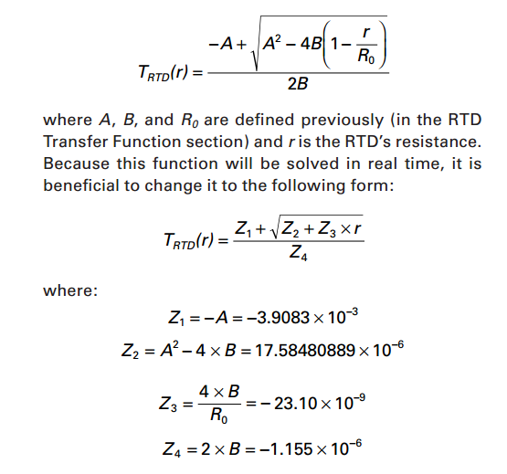
1. The first method uses mathematical equation to derive the temperature.
The linearization equation is given as:
Rt = R0 * (1 + A* t + B*t2) for temperature > 0°C
Where:
Rt is the resistance at temperature t, R0 is the resistance at 0 °C, and
A= 3.9083 E–3
B = –5.775 E–7
Solving the equation gives as:
2. The second method uses lookup table for the resistance vs temperature values.
Thanks to K.C. Lee for helping me figure out this method.
All the required files are attached with the project.
Using RTD COEFFICIENT GENERATOR TOOL provided by Analog Device, we can generate the look up table and it can be incorporated in the design very easily .
So, Now I just need to find out the resistance of PT100.
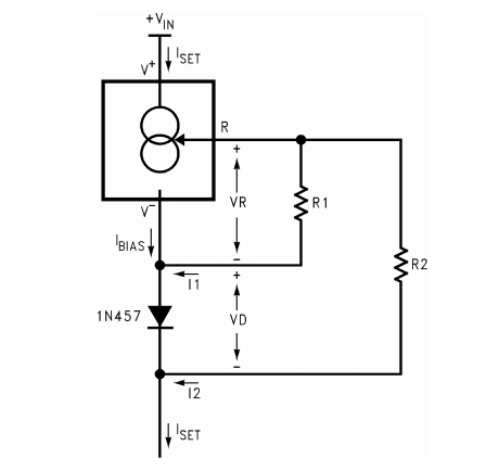
For determining resistance, I used constant current source IC LM334. The circuit is as shown in following diagram. This circuit will eliminate most of the LM134's temperature coefficient.
ISET is the current through load, which is given by the equation:
Iset = 0.134/R1
and R2 = 10*R1
To avoid self heating of the sensor the power decipation in the sensor shold be less than 0.6mW. So I will be driving 1mA of current through sensor to keep the power at 0.3mW (at 600°C).
Considering tolerance of resistance and CCS, It may not be exactly 1mA. So I will be adjusting the tolerance by calibrating in software.
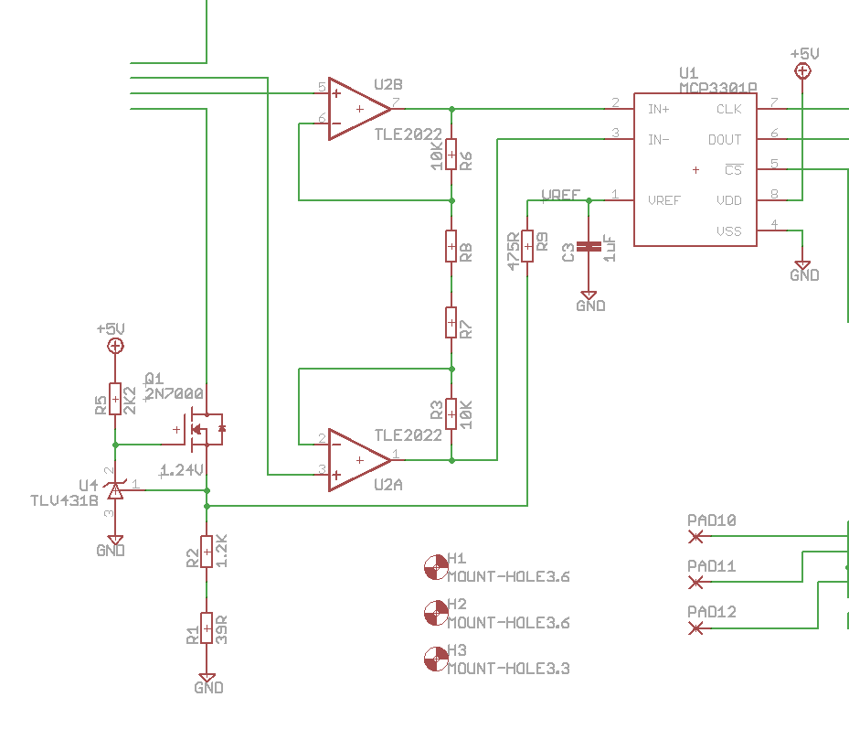
Considering, 1mA current will be flowing through PT100, and thus we can get 1mV change in volage for each 1ohm rise in resistance of sensor.
Considering the required range from 0°C to 600°C, the resistance will be varying from 100Ohm to 313.74Ohm, thus giving the voltage range from 100mV to313.74mV., which is not a big range to play with.
For this, I will be using Op Amp in non-inverting mode with the gain of 15, so as to have a range 1500 mV to 4706.1 mV. This would give the total range of 3206.1 mV for 600, this would result in 5.3435 mV per degree rise in temperature.


 Lithium ION
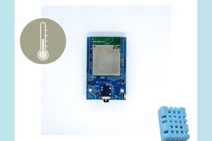
 Daphne
 Andrey Bykanov
 Scott Clandinin
Hi Lee, Thank you very much for the input.
As i am in still development and trying out the all the things possible to choose the best one.
If I just put one resistor in series with the sensor and applies it to ADC, and I am going to use inbuilt 10 bit ADC of AVR, then resistor value needs to be very much close to the sensor value that is resistor<500 ohm for good accuracy and for more resolution then I think I will have to deal with sensor self heating problem. I plan to use a low cost constant current source IC LM334 for the same purpose. Also this CCS current does not depend on the supply voltage.
I was also referring the same the AN-709 but could not find the tool for generating the table. After your comment I searched it more deeply and found the same. I generated the C file using tool and it seems to be very much easy to incorporate the generated file. Thanks again for the help. Still I will list out here both the methods.