 Martin Cejp
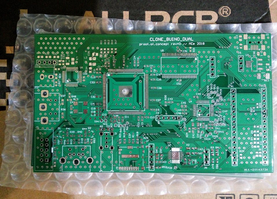
克隆BUINO DUAL不是软件模拟器。 我们的控制台使用FPGA实现最高保真度。 目前我们正在准备Board版本0来测试我们的想法并丰富RTL。 未来,我们打算通过使用合适的芯片来降低成本。 所以每个人都可以有时间玩。Cloning BUINO DUAL is not a software simulator. Our console uses FPGAs for maximum fidelity. Currently we are preparing Board version 0 to test our ideas and enrich RTL. In the future, we intend to reduce costs by using suitable chips. So everyone can have time to play.
0%
0%
CLONE BUINO DUAL
兩個控制台模擬器 Two console simulators
Become a Hackaday.io member
Already have an account? Log in.
Just one more thing
To make the experience fit your profile, pick a username and tell us what interests you.
Pick an awesome username
hackaday.io/
Your profile's URL: hackaday.io/username. Max 25 alphanumeric characters.
Pick a few interests
Projects that share your interests
People that share your interests
 greg
greg
 Saimon
 Dave
Dave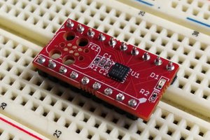
 Parker