The idea of time is simple, yet complex. In its simplest form, it’s the counting of a regular, repeating pattern. On the opposite end, we would have to turn to Einstein. Thankfully, this story resides on the simple side. You see, before the advent of the Real Time Clock, electrical engineers scurried hither and yon in search of ways to accurately calculate time in their circuits. One very convenient source of a regular, repeating pattern was the 60 Hertz line frequency coming from the wall outlet. It was a very stable source in the US. And so long as it was stable, your machine would work fine. But if ever a crack appeared in the stability of the 60 Hertz, the entire machine could be compromised.
And so was the case on the idle Tuesday morning our story begins. Giant pillars of white smoke soared high in the air from the large, concrete stacks that reached up into the clear blue sky. It was easy to find parking in the large lot when I arrived at the paper making plant nestled on the outskirts of Richmond, Virginia. The smell of sulfur was thick, and the rumble of the large trucks carrying trees filled the air as they entered the plant. It was a short walk to the visitor’s desk, where I was met by the man who had called me a few days earlier.
“………damn thing doesn’t work,” he had said. I get that a lot. He led me to the not working microwave solids analyzer. These machines are simple, and consist of a microwave, balance and embedded computer. It heats a sample to remove all the moisture, and the computer uses the difference in weight to calculate the percent moisture in the sample.
I placed a test sample in the machine and pressed the start button. Immediately, problems were apparent. On the grey scale display, the system clock was counting down the time. The problem was, it was counting way too fast. It had counted down over two minutes. But my gut, verified by a clock on the cinder block wall, told me that less than a minute had gone by. I pressed the stop button, and another problem revealed itself. Instead of the usual single beep, I got three. It acted as if I pressed the button a couple times, instead of just once. It appeared I had debouncing problems as well as timing issues. It was then that I clued in on the A/C line, and took a closer look. I was in for a shock.
Video 1
Figure 1
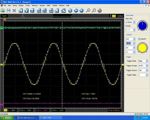
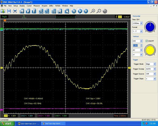
The above video and scope screen captures were taken directly from the 120 volt wall socket via a 10 to 1 step-down “wall wart” transformer using a 10x probe. As you can see, the signal is very dirty. I concluded the source of the noise was probably from one of the large paper rolling machines running elsewhere in the plant.
I had identified the problem. But I still did not know - a) how the dirty signal was causing the timing and debouncing issue and - b) how to fix it.
I had to solve “a” before I could even begin to approach how to fix the issue. So like any good tech, I dug into the schematic. It wasn’t long until I discovered a small circuit that appeared to be converting the A/C line frequency into a 5 volt clock signal. The output of which was routed to one of the pins of the 80188 Intel processor.
Figure 3
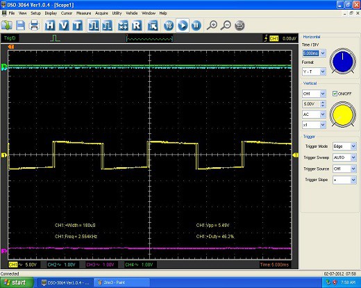
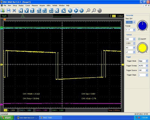
When I saw this, I knew I had to get a scope on PIN 6 of the opto-coupler (U7) to see if the noise on the A/C line was getting through.
Figure 4
Figure 5
So the noise from the A/C line was getting through the opto-coupler in the form of problematic leading and trailing edges. It was so bad, that the scope had a hard time locking on to the frequency, as seen in Figure 4.
I did not have access to firmware, but my theory was sound. I believed that the 80188 computer was using this very signal to generate its definition of time – every 120 leading edge counts was equal to one second in the firmware. And in this case, all of the spikes on the leading edges were being counted as well. This would cause the system’s internal clock to run too fast. Also, I knew the switch debouncing was done in firmware. This code is dependent on accurate delay times. If the system clock is running too fast, that means the delay times would be too short, and as a result the debouncing code was not working properly.
YESSSS! I had found the source of the problem, theoretically at least. Now, how to fix it...
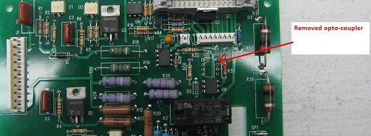
Long story short, I concluded that it would be easiest to simply replace the signal. I would remove the opto-coupler IC, and use a microcontroller to generate a clean signal and route it to the processor.
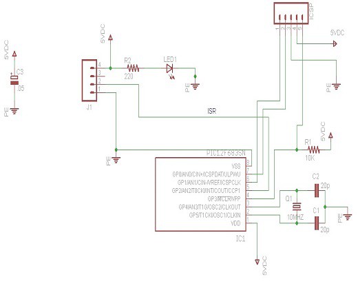
Figure 6
Above is the schematic. (I realized I had taken the scope readings, figures 4 and 5, off U6 instead of U7. U7 produces a 10% duty cycle 120Hz signal, as opposed to 50%.)
Below is the code to generate the 120 Hz 10% duty cycle signal.
while (true) { {output_high(PIN_A2);
delay_us(833);
output_low(PIN_A2);
delay_us(7600);
}
}
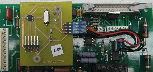
I made a board using toner transfer. I removed the opto-coupler, and used the empty socket to supply power to my board and route the clean signal to processor.
Figure 7
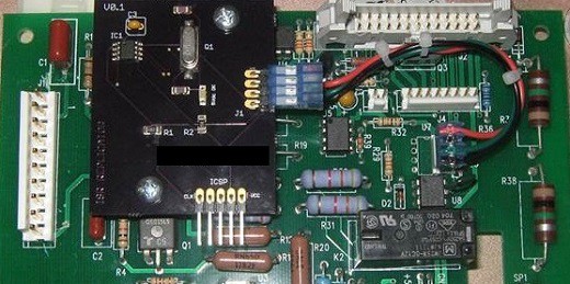
Figure 8
I installed it in the instrument the next day, and everything worked perfectly! The timing was accurate and no more debouncing issues!
I had the board done from a board house and installed it a few weeks later. The instrument has been working well ever since.
 will.sweatman