engunneer
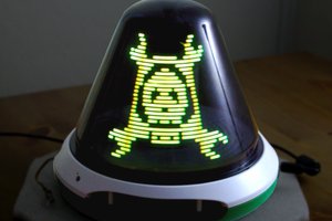
The final product is a assembly of 9 PCBs for the display and a Teensy 3.2 to drive everything. Future work will include a RaspPi or similar to run the processing code.
I've actually been working on this for nearly a year, so I'm slowly catching up on project logs below.


 zakqwy
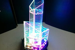
 bveina