 Neo
Neo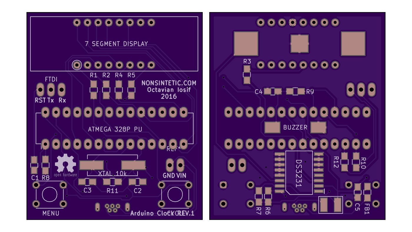
Having managed to get a working schematic together I decided to put it together as much as possible on the breadboard. This means switching out the I2C display with a plain old common anode display from Pimoroni, using an ATMega328P-PU chip straight on the board and powering it from a USB breakout. I couldn't find a way to test the RTC part without the breakout for it, it's way too small to use outside of a PCB, so that part will remain a mystery till the custom board arrives.
Multiplexing the display was much simpler than I expected, although finding a full-featured library for this task was a pain in the butt, most of them only let you input a number and that's that, no colon or AM/PM indicator (hyphen as it's sometimes referred to) support on any library that I could find and most of them don't have proper brightness control. In any case I went with the SevSeg (why are there so many libraries named this?) from Dean Reading. I had to change it because I couldn't live with just inputting numbers into it, I added two functions, one for passing an array of Byte values to change all the digits at once (so I could write other stuff than just numbers) and one to set a particular digit using a byte value.
The way multiplexing usually works in these 7 segment multiplexing libraries (including the i2c display library from Adafruit) is you store the on/off state of each segment (led) in a digit in a single byte value (8 bits = 7 segments + the colon), aka B01111111 would display an 8. The first bit is the colon on the digit, the other 7 are the a,b,c,d.. segments on the digit. 1 would be on and 0 would be off, obviously. Then the loop reads the required bit from each segment's byte value for each segment at a time and lights it or not. For example, in one iteration of the loop the script would check the on/off bit for the 'a' segment on all the digits, display it or not (simultaneous on all digits), wait a number of milliseconds (more = more brightness), then moves on to the 'b' digit etc. This way of doing it means you can put the current limiting resistors on the common anodes/cathodes of the display (the pins that control the digit, not the segments) resulting in less resistors.
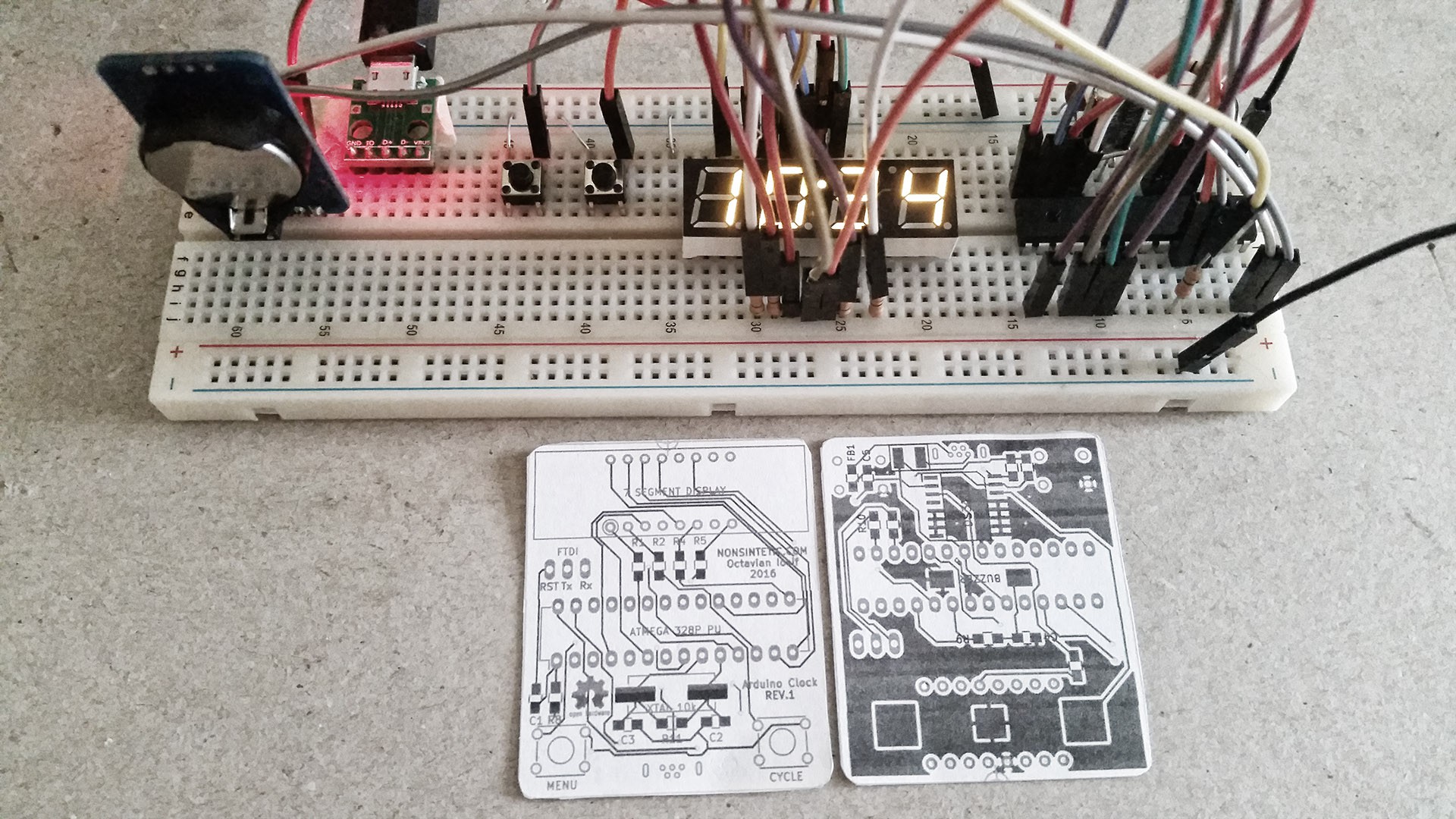
Above you can see the whole thing put together on the breadboard (it's basically just a barebones Arduino setup + a display, RTC, buzzer and buttons). Next to it there's a 1:1 print-out of the custom PCB I designed for it. As you can see it's quite small (and messy since I did it in one night). This was the first time designing a PCB for me, it was an amazing process, great fun.
Once you set up the design rules for your project ( I got mine from the OSHpark website, since I'm going to be using their services to fabricate the PCB) it's just a matter of finding all the parts you need on Farnell or Digikey or whatever website.
Once all the parts have been selected, you can go through each one and see if there's a footprint in your CAD program's libraries, if not you can look for one online, but usually it's really easy to make your own footprint, all serious part manufacturers give you a drawing of what the pads have to look like on the PCB, then all you have to do is reproduce the drawing they give you in your CAD footprint editor (took me around an hour to find all the parts and make footprints for the chips, buttons, battery holder and buzzer in KiCAD).
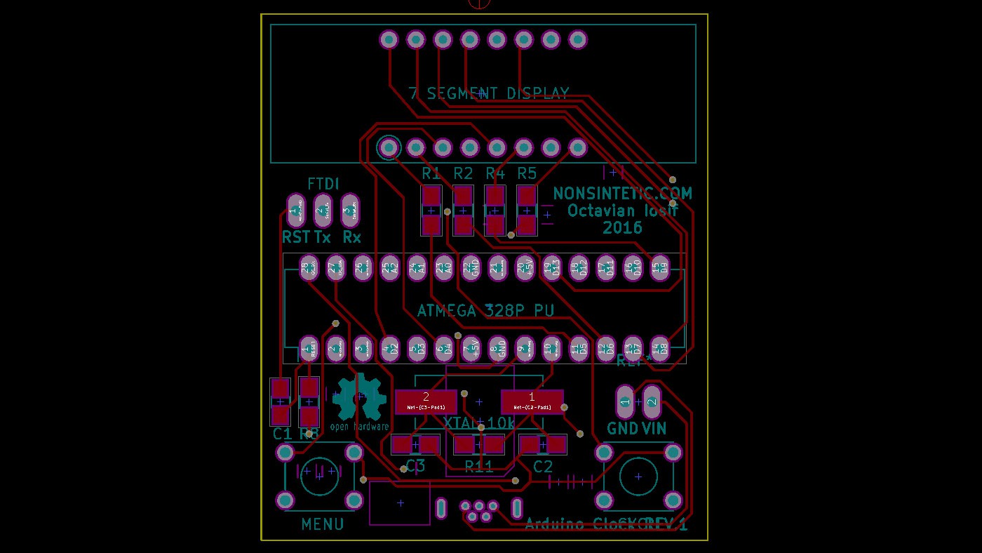
The design I sent out is pretty crap, there's a rats nest of traces going everywhere, but I just wanted to get it out there and see if it will work, if it works I'm going to do a rev. 2 where I make it nice and elegant. Another problem I had was, since I was lazy and did a lot of the traces on the back of the board too, the ground plane on that side was messed up and full of little islands I had to go through and make sure are connected to the main ground, the way professionals usually do PCB design is they put as much as humanly possible on the front side where it's just traces and have the back for only a few traces and the ground plane, aw well... I did take an extra hour to follow all the traces by hand with a pencil on the print-out so I can be sure everything is correct (the CAD software shows you unconnected stuff, but it's always good to check the pin order on the chips and polarities and stuff, parts from libraries CAN sometimes have inverted pins and that will ruin your day).
Discussions
Become a Hackaday.io Member
Create an account to leave a comment. Already have an account? Log In.