 hanno
hanno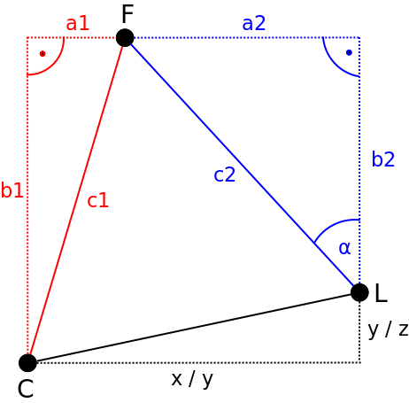
vertical air flow (depending on looking from either the top or the side) into the direction of the face. By exploiting the two additional triangles drawn in red and blue, one can apply some simple trigonometric computations to derive the servo motor angle α.
Computing the distance to the face (c1)
In order to compute the distance to the face c1 in a camera image one first needs to determine the focal length F of the camera.
Determining the focal length F of the camera
Assuming a pinhole camera model, the focal length
F can be obtained by recording an object with a known width W with a distance D with the camera. After determining the apparent width of the object in pixels P, one can compute the perceived focal length F of the camera according to the following formula:
E.g. if we place a ball with a diameter/width W=10 cm and a distance D=100 cm in front of our camera and measure an apparent width of the ball in pixels P=20, then the focal length of our camera is:
Please note: As the horizontal and vertical focal lengths of the camera f_x and f_y are already contained in the camera matrix obtain from using OpenCVs camera calibration tool, one can simply use
them instead of performing the calibration procedure outlined above.
After having obtained the focal length F the distance to the face c1 can be computed using triangle similiarity:
Finding the distance to a face c1 using triangle similarity
Assuming we have found the focal length F of our camera in the previous step, we can now compute the distance c1 to an object (e.g. a face) with a known width W using the so-called triangle similarity:
As an example, I will assume the average width of a face is W=14 cm. If a face has been detected in the camera image and and the apparent width of the face in pixels is P=25, the distance to the face can be computed by taking the focal length F of the camera into account:
Hence, the distance c1 to the face is 112 cm.
Determining the distance of the face from the center optical axis (a1)
After having determined c1 the distance of the face from the center optical axis a1 of the camera can be computed. Assuming an average width of a face W in cm, the width in pixel of the face detected in the camera image P and the position of the center of our face in pixel C, one can compute a1 according to the following formula:
where i represents the horizontal (or respectively vertical) resolution of the camera image in pixels. w corresponds to the width of the bounding box surrounding the face in pixels obtained from the face recognition algorithm.
Determining the servo motor angle α
After having determined c1 and a1 in the red triangle the servo angle α can be derived from simple Pythagorean equations. The corresponding formulas for determining the horizontal servo angle are shown below:
After having calculated the lengths a2, b2 and c2 of the blue triangle the servo motor angle α can now be determined by the following formula:
The FaceToPosition Class
The calculations described above are implemented in the FaceToPosition class. Once instanced the corresponding object takes the width of the face, the position of the bounding box around the face and the focal lengths of the camera lens into account in order to estimate the position of the face relative to the camera and computes the relative servo angles for the horizontal and vertical lamellae of the fan accordingly. The following video shows the code in action:
The code is available via my GitHub repository.
Discussions
Become a Hackaday.io Member
Create an account to leave a comment. Already have an account? Log In.