 Christoph
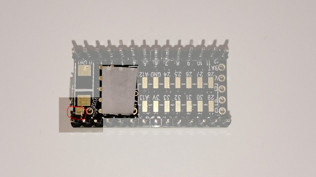
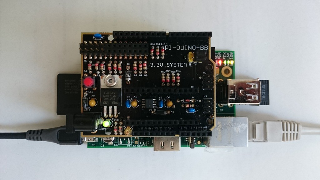
First, let's see if it's even possible to use the Teensy as an I²C slave to the pi if they're connected through the Pi-Duino-Teensy board (I'll call it PDT from now on). According to the schematic, the Teensy's I²C pins (A4 - SDA and A5 - SCL) are connected to the pi's I²C pins (GPIO3 - SDA and GPIO5 - SCL) through 220 ohm resistors. I've never used inline resistors in I²C lines, but I don't think they will cause major problems.
Pull-ups? The PDT doesn't have any and iirc the pi has 1.8 kOhm on each I²C line. That's ok, I think.

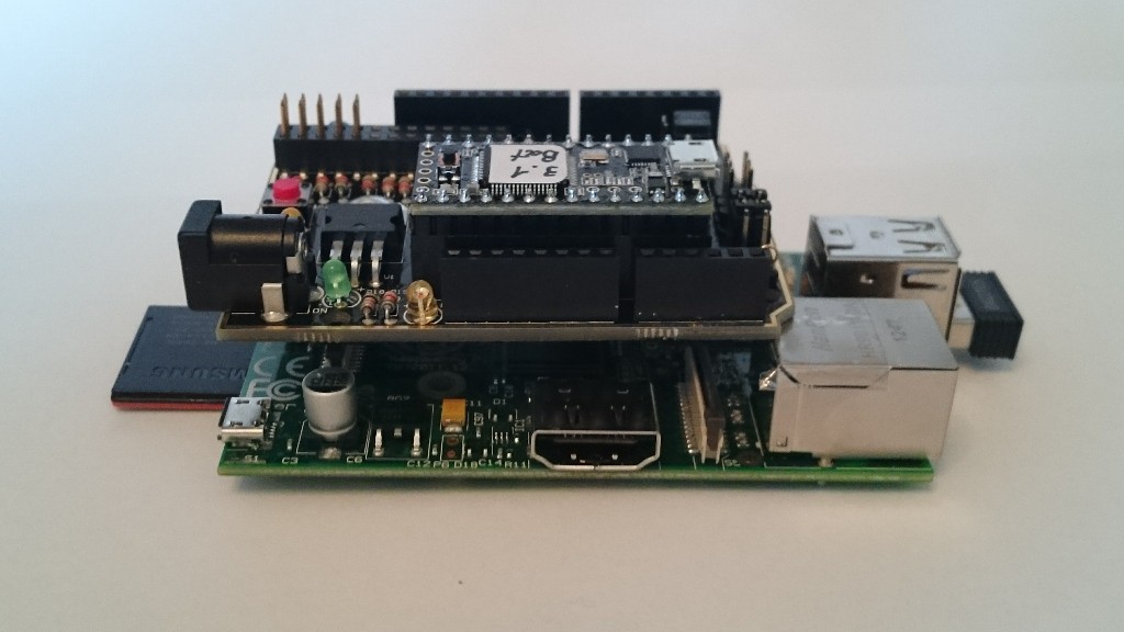
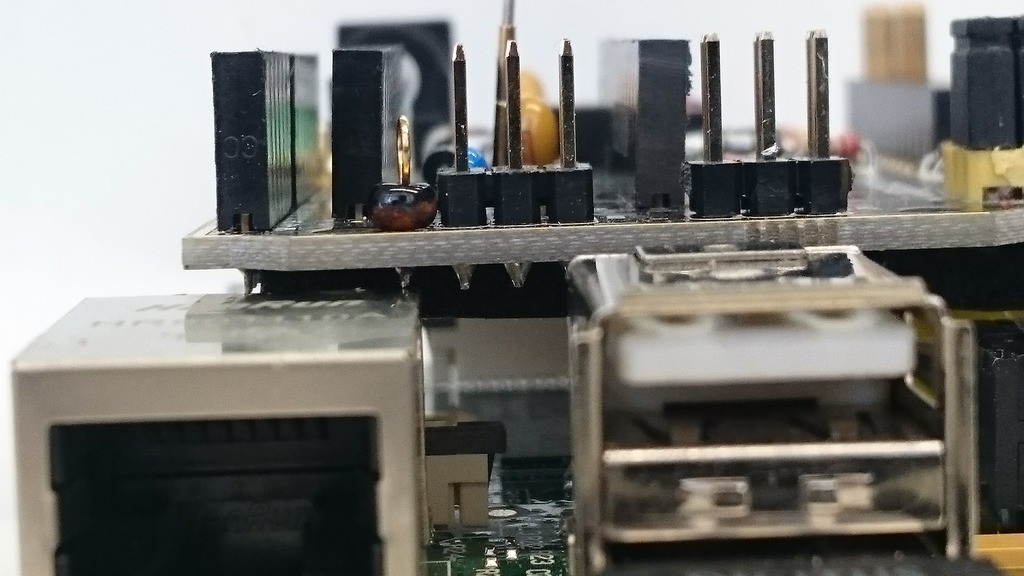
 H3 is used to connect either the Teensy or the RPi with the arduino headers. Too bad I want to connect the Pi with the Teensy, but there's a workaround. I configured the header for Teensy <-> arduino, and then used two jumper cables to connect RPi <-> arduino:
 There are a few familiar headers I'd like to start with:


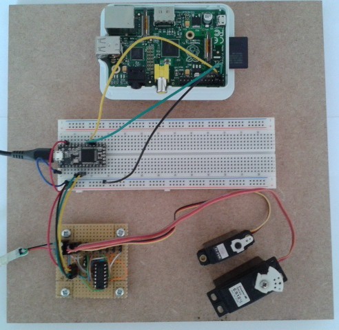
 And tested it with simple code that simply sets the servo outputs to a fixed value. Here's the hardware:
 I used the Bus Pirate's on-board pull-ups with VPullup connected to the Teensy's 3.3 V output. It's been the first time I used that feature and it worked flawlessly.
 Two screw terminals for the servo supply, female header for the Teensy connection (3.3 V, Frame, Tx and Gnd) with optional screw terminals, decoupling cap (not labeled), and a jumper to choose the supply for the shift register (it can be powered by the servo supply or by the teensy).
 Gergely Imreh
 Salvatore
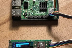
 Poyu Chen