 DrYerzinia
So after changing to the new microcontroller most things where the same. Same power supply, same RF module but as can be expected I made more mistakes.
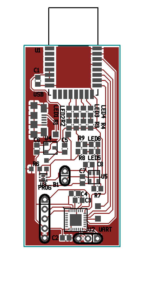
Its a nice and clean single sided layout with only 3 jumpers.
First off, like an idiot I assumed remappable pins meant any pints for any function on any module like it is in most pic controllers with remappable pins. But if I had read the pin IO descriptions I would have seen that the SERCOM on these chips have spesific sets of pins they can be on with specific function muxes. Fortunately I was only off by 1. Cutting and flipping 2 traces on the SPI bus and I was golden. I got lucky that the UART was ok.
The second issue was with the charge circuit. I noticed it drawing more current than expected to charge the battery so I took a look at the schematic and the FET/Diode I was using to switch to external power. When I had drawn the symbol for that part I had neglected to draw the body diode of the FET. I had the battery on the wrong side and it was letting current from the 5V USB rail flow strait into the battery. Well that was just great no battery for this board.
Finally I was experiencing periodic issues communicating with the DWM1000 over the SPI bus. It wasn't responding properly to commands. My best guess was some kind of reset issue. You can see the bodged in an NPN transistor for the reset line of the DWM1000. I tried to just assert the IO pin low but in sleep mode it caused issues so the NPN.
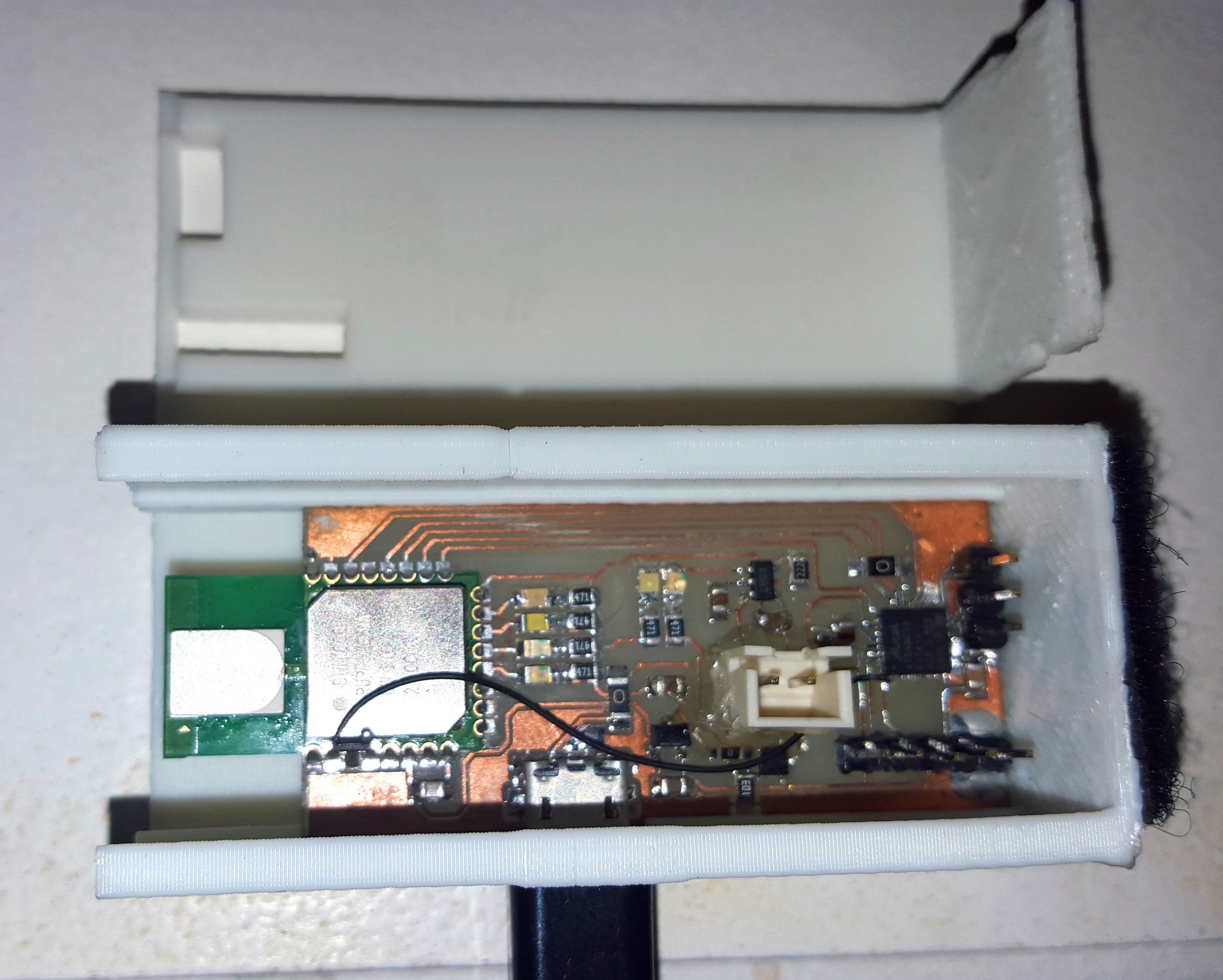
I also printed a nice case for it that slides together. Sadly the API command to enable the DWM1000 LEDs didn't seem to work. No blinks.
Overall it came out quite nice. I did have some strange issues with the soldering on the QFN. I've never really had issues soldering QFN's but this time around I did have some strange bugs. I recently switched from using leadless to leaded solder after reading a nice long NASA paper on the subject and it was quite finicky. Normally I tin the pins and then drop it in place with the hot air but it didn't seat quite right. That might have just be the lack of solder mask. But then I went back and bumped each of the edges with some leaded solder and flux and got most of the connections looking solid. Inspite of this there where still some issues with contact and I found I got the UART working again after I pressed down on the solder fillet on the edge of the chip with one of my multimeter probes. All worked out in the end.
Discussions
Become a Hackaday.io Member
Create an account to leave a comment. Already have an account? Log In.