 Jeremy g.
So I have managed to finish the bootloader, this includes the verification step in the python script.
Since I have been presented with some better information I will document the process of using the bootloader in more detail here.
Currently the bootloader version is 1.3 and can be found on github through the link on the left side of the page.
Setting up atmel studio 7
Start by creating a new project.
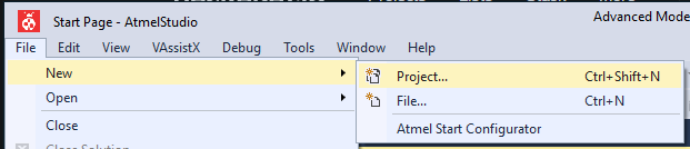
Name your project and select GCC C Executable Project.
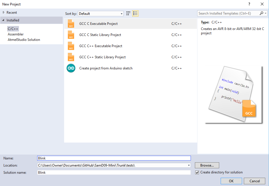
Select the proper chip family, in our case SamD09.
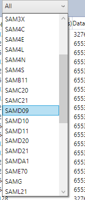
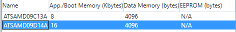
Select the chip present on the board, if you use @al1's board you would select ATSAMD09C13A. You will also need to wire the DTR pin from the ch340g(pin 15) to PA15, without this you will not enter bootloader mode. (hope its ok i used your board as an example.)
If using the MiniSam-Zero those connections are already made.
Once atmel studio has completed setting up your project. Right click on your project in the right panel and select properties. You should see this window. If you do not, you right clicked on the wrong item. usually the 2rd entry down.
Now we need to tell the linker that we want the program to start at address 0x800. This will make the program compatible with the miniSam bootloader. Find ARM/GNU linker and select Miscellaneous. Copy the code given below into the field Linker Flags.
-Wl,--section-start=.text=0x800Then click ok. Now you can select your main.c in the right panel and start coding.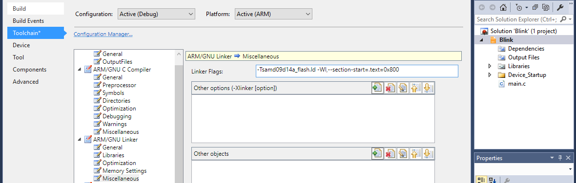
a simple blink app.
#include "sam.h"

void init_TC1(void)
{
	//Thank you Al1 for sharing this timer setup.
	//setup clock for timer/counters
	REG_GCLK_CLKCTRL = GCLK_CLKCTRL_CLKEN | GCLK_CLKCTRL_GEN_GCLK0 | GCLK_CLKCTRL_ID_TC1_TC2;
	REG_PM_APBCMASK |= PM_APBCMASK_TC1;
	REG_TC1_CTRLA |=TC_CTRLA_PRESCALER_DIV8;			// prescaler: 8
	REG_TC1_INTENSET = TC_INTENSET_OVF;					// enable overflow interrupt
	REG_TC1_CTRLA |= TC_CTRLA_ENABLE;					// enable TC1
	while(TC1->COUNT16.STATUS.bit.SYNCBUSY==1);			// wait on sync
	NVIC_EnableIRQ(TC1_IRQn);							// enable TC1 interrupt in the nested interrupt controller
}

void TC1_Handler()
{
	REG_PORT_OUTTGL0 = (1 << 14);						// toggle led PA14
	REG_TC1_INTFLAG = TC_INTFLAG_OVF;					// reset interrupt flag - NEEDED HERE!
}

int main(void)
{
    /* Initialize the SAM system */
    SystemInit();
	init_TC1();											//init the clock.
	REG_PORT_DIR0 = (1 << 14);							//set the direction to output of PA14

    while (1)
    {
    }
}
This code should blink the on board led at 1hz. Here's how to upload it to the miniSam bootloader.
Uploading.
As a note, the python script requires that you have python 2.7 installed as well as pyserial. Python 2.7 download. This link is directly from python.org's download section.
Currently the miniSam bootloader uses a python front end, I did not code this entire front end. This front end came with the suggested non working bootloader on a forum post and I updated it and modified it. So i can not take credit for this one. I will take credit for the modifications though :)
open a command line and navigate to the bootloader directory like so.

The python script you will be using is called upload.py instead of what is currently in the picture. The options are -c com# -b baudrate -i yourfilename.bin
If you have entered all of that properly you will presented with a quick question.

This question will ensure the miniSam bootloader is loaded and active. type y to proceed. Its fast but you will see a lot of programming page # and verifying page #
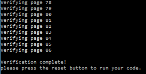
That's it your done!. Hopefully this is not to painful :), now you have no reason not to pick up a Arm micro (SamD variant at this point) and have some fun.
(Demo video will be here later. once its done uploading.)
I will be making some mini libraries I think, maybe. I'll see whats already out there.
until next time stay happy, stay healthy, and keep hackin.
Discussions
Become a Hackaday.io Member
Create an account to leave a comment. Already have an account? Log In.
In your bootloader I would add a line at the beginning of your main(). The pull resistor gets enabled there. By default it is a pulldown. So that you enter the bootloader also if nothing is connected to the boot pin. By adding:
PORT->Group[BOOT_PORT].OUTSET.reg = (1<<BOOT_PIN);
You get a pullup resisiotr. This at least form me more useful. If the boot pin is connected to DTR also no pull resistor should be possible.
Are you sure? yes | no
I think I had that at one point but it was causing issues. I'll look at it again and see what's going on with it.
Thanks.
Are you sure? yes | no
I do not know if it work with the CH340's DTR pin. I think it should. But so far I always pulled PA15 manually down to enter the bootloader mode.
Are you sure? yes | no
if need be you can set the DTR pin in different states in the python script. Look for ser.setDtr (True) and change to see if that fixes it. Pretty sure the DTR pin acts the same on both the ch340g and the cp2102.
Are you sure? yes | no