 AndrewMcDan
I've spent the past couple days working various parts of this project, and I have completed the controller for the climate control system.
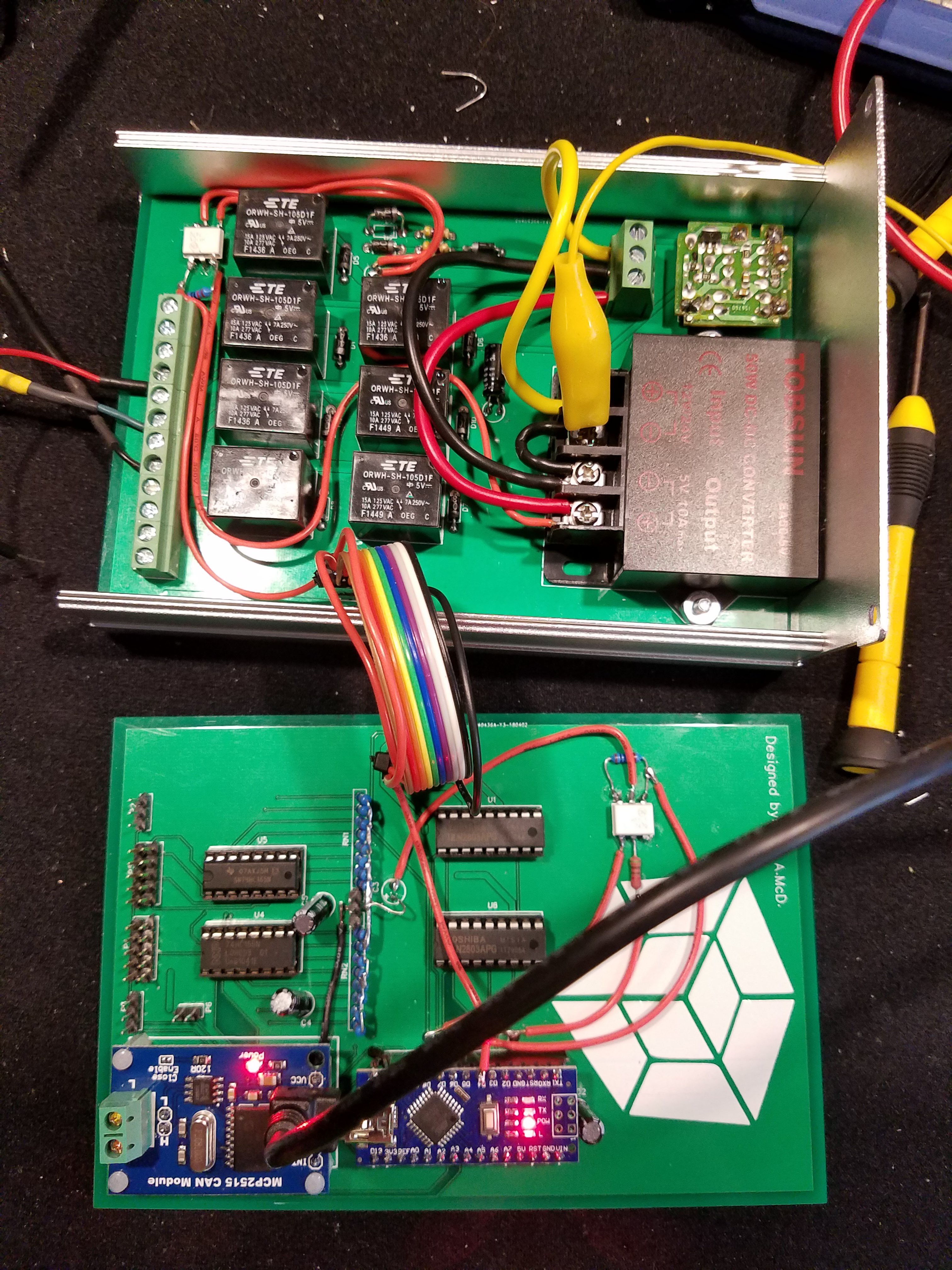
Relays for controlling the fan, 5V DC-DC switched power supply, timer circuit from the original rear-window-defrost, CAN-bus controller, and an Arduino. The headers on the left of the bottom board are for the servos and encoders that interface with the OEM push-pull cable system.
Here's the code for the Arduino:
#include <Servo.h>
#include <mcp_can.h>
#include <SPI.h>
#include <EEPROM.h>


#define CAN_INT 2
#define AC_STATUS 5
#define SERVO_2 6
#define SERVO_1 7
#define LOAD_DATA 8
#define CLK_INH 9
#define CAL_BTN 3
#define FAN_SET1 A0
#define FAN_SET2 A1
#define FAN_SET3 A2
#define FAN_SET4 A3
#define DEF_TOG A4
#define AC_EN A5
#define RECIRC_EN A6
#define AC_STATUS_ANALOG A7
#define DEF_STATUS 4


MCP_CAN CAN0(10);
bool CANgood = false, def_toggle = false, AC_enable = false, recirc_enable = false;
long unsigned int rxId;
unsigned char len = 0;
unsigned char rxBuf[4], txBuf[4];
Servo servo1, servo2;
unsigned int encoders1 = 0, encoders2 = 0;
int numberOfPositions_1 = 0, numberOfPositions_2 = 0;
byte fans = 0, temp_1 = 0, destination = 0;
unsigned long time = 0,time2=0;

void setup() {
  Serial.begin(115200);
  pinMode(CAN_INT, INPUT);
  pinMode(AC_STATUS, INPUT);
  pinMode(DEF_STATUS, INPUT);
  pinMode(SERVO_2, OUTPUT);
  pinMode(SERVO_1, OUTPUT);
  pinMode(LOAD_DATA, OUTPUT);
  pinMode(CLK_INH, OUTPUT);
  pinMode(CAL_BTN, INPUT_PULLUP);
  pinMode(FAN_SET1, OUTPUT);
  pinMode(FAN_SET2, OUTPUT);
  pinMode(FAN_SET3, OUTPUT);
  pinMode(FAN_SET4, OUTPUT);
  pinMode(DEF_TOG, OUTPUT);
  pinMode(AC_EN, OUTPUT);
  pinMode(RECIRC_EN, OUTPUT);

  digitalWrite(FAN_SET1, LOW);
  digitalWrite(FAN_SET2, LOW);
  digitalWrite(FAN_SET3, LOW);
  digitalWrite(FAN_SET4, LOW);
  digitalWrite(RECIRC_EN, LOW);
  digitalWrite(AC_EN, LOW);
  digitalWrite(DEF_TOG, LOW);
  digitalWrite(CLK_INH, HIGH);
  digitalWrite(LOAD_DATA, HIGH);
  //digitalWrite(CAL_BTN, HIGH);

  servo1.attach(SERVO_1);
  servo2.attach(SERVO_2);


  if (CAN0.begin(CAN_1000KBPS) == CAN_OK) {
    CAN0.init_Mask(0, 0, 0x7Ff);
    CAN0.init_Mask(1, 0, 0x7ff);
    CAN0.init_Filt(0, 0, 0x00e); // climate control data
    CAN0.init_Filt(2, 0, 0x00e);
    CAN0.init_Filt(3, 0, 0x00e);
    CAN0.init_Filt(4, 0, 0x00e);
    CAN0.init_Filt(5, 0, 0x00e);
    Serial.print("can init ok!!\r\n");
    CANgood = true;
  }
  else {
    Serial.println("not ok");
    //while (true) {}
    Serial.println("continuing");
  }


  if (!digitalRead(CAL_BTN)) {
    Serial.println("calibration");
    calibrateEncoders();
  }
  for (int i = 0; i < 4; i++) {
    txBuf[i] = 0;
  }
}

void loop() {
  // every 500 ms, send an update to the main controller
  if ((millis() - time) > 500) {
    time = millis();
    txBuf[0] = txBuf[0] | fans;
    txBuf[0] = txBuf[0] | (def_toggle << 4);
    txBuf[0] = txBuf[0] | (AC_enable << 5);
    txBuf[0] = txBuf[0] | (recirc_enable << 6);
    txBuf[1] = temp_1;
    txBuf[2] = destination;
    txBuf[3] = analogRead(AC_STATUS_ANALOG)>300?1:0 | (digitalRead(DEF_STATUS) << 1);
    CAN0.sendMsgBuf(0x7ff, 0, 4, txBuf);
    Serial.print("AC status: ");
    Serial.println(digitalRead(AC_STATUS));
    Serial.print("Defroster Status: ");
    Serial.println(digitalRead(DEF_STATUS));
    Serial.println("");
  }

  // This is here for testing purposes
  /*if((millis()-time2)>5000){
    time2=millis();
    //def_toggle = true;
    recirc_enable = !recirc_enable;
    AC_enable = !AC_enable;

    if(fans==16){
      fans=0;
    }else if(fans==0){
      fans=1;
    }else{
      fans = fans << 1;
    }
  }*/

  // If the CAN bus has new data for this controller, read it an do stuff with the data
  if (!digitalRead(CAN_INT) && CANgood) {
    CAN0.readMsgBuf(&len, rxBuf);
    rxId = CAN0.getCanId();
    if ((rxId == 0x00e) && (len >= 3)) {
      fans = rxBuf[0] & B00001111;
      def_toggle = rxBuf[0] & B00010000;
      AC_enable =  rxBuf[0] & B00100000;
      recirc_enable = rxBuf[0] & B01000000;
      temp_1 = rxBuf[1];
      destination = rxBuf[2];
    }
  }

  // we only want to turn on one of the fan signals at a time, so check to make sure that only one bit is set high or all are low
  if (countSetBits(fans) <= 1) {
    digitalWrite(FAN_SET1, fans & B00000001);
    digitalWrite(FAN_SET2, fans & B00000010);
    digitalWrite(FAN_SET3, fans & B00000100);
    digitalWrite(FAN_SET4, fans & B00001000);
  }

  // send a pulse to the defrost timer
  if (def_toggle) {
    digitalWrite(DEF_TOG, HIGH);
    delay(200);
    digitalWrite(DEF_TOG, LOW);
    def_toggle = false;
  }

  digitalWrite(AC_EN, AC_enable);
  digitalWrite(RECIRC_EN, recirc_enable);
  updateServos(temp_1 , destination );
}

bool updateServos(byte servo_1_pos, byte servo_2_pos)
{


  // A lot goes on in the next few lines of code
  // starting with new position variables and working outwards:
  // these two variables are in the range of 0 to 255 so lets map it to a new range.
  // the new range is from 0 to whatever the caliration set as the max position.
  // the calibration set the max position in EEPROM in the last two addresses.
  // once the mapping is complete, we read the current encoder data and use that as the address
  // to look up what the current position is.
  // to make sure we are working with good values, lets contrain this position values that are
  // between 0 and the max position as read from the last two addresses in EEPROM.
  // subtract our mapped int from the current position to get our offset.
  // multiply this offset by 10 so that the servo speed will be quick.
  // constrain maximum servo speed to +/-30.
  // add 90 because that is the "stop" speed.
  // write to the servo.


  byte len = EEPROM[EEPROM.length() - 1] - 2; // stay 2 positions away from edge
  byte currentPos = EEPROM[highByte(read74HC165())];
  if (currentPos != 255) { // check for out of bounds value (255) prior to updating servo
    servo1.write(
      constrain(
        (
          currentPos
          - map(
            servo_1_pos, 0, 255, 2, len // stay 2 positions away from edge
          )
        ) * 10 , -30, 30
      ) + 90
    );
  } else {
    return false; // hit out of bounds
  }
  len = EEPROM[EEPROM.length() - 2] - 2;
  currentPos = EEPROM[lowByte(read74HC165())];
  if (currentPos != 255) {
    servo2.write(
      constrain(
        (
          currentPos
          - map(
            servo_2_pos, 0, 255, 2, len
          )
        ) * 10 , -30, 30
      ) + 90
    );
  } else {
    return false;
  }
  return true;
}


//======================================================================
// Reads two bytes from the 74HC165 registers
unsigned int read74HC165()
{
  digitalWrite (LOAD_DATA, LOW);        //load the push button state into the 74HC165
  asm("nop\n nop\n");              //some delay
  digitalWrite (LOAD_DATA, HIGH);
  digitalWrite (CLK_INH, LOW);        //enable 74HC165 clock
  asm("nop\n nop\n");              //some delay
  unsigned int Switches = SPI.transfer16(0); //get the position
  digitalWrite (CLK_INH, HIGH);       //disable 74HC165 clock

  return  Switches;                //switches will have the value read by then 74HC165
}
//       END of read74HC165()
//======================================================================


void calibrateEncoders() {
  for (int i = 0 ; i < EEPROM.length() ; i++) {
    EEPROM.write(i, 255);
  }

  while (!digitalRead(CAL_BTN)) {}
  Serial.println("Starting Clibration of number 1.");
  Serial.println("Press button when reaching start point.");
  delay(2000);
  servo1.write(100);
  while (digitalRead(CAL_BTN)) {}
  servo1.write(90);
  Serial.println("end position noted");
  byte encoder_1 = highByte(read74HC165());
  byte encoder_2 = encoder_1;
  int pos = 0;
  delay(2000);
  Serial.println("Other direction");
  delay(1000);
  servo1.write(80);
  while (digitalRead(CAL_BTN)) {
    int tester = countSetBits(encoder_1 ^ encoder_2);
    if (tester > 1) {
      Serial.println(tester);
    }
    if ((tester == 1) && (EEPROM[encoder_1] != EEPROM[encoder_2])) {
      //Serial.println(encoder_1, BIN);
      //Serial.println(pos);
      servo1.write(90);
      delay(5);
      EEPROM[ encoder_1 ] = pos;
      encoder_2 = encoder_1;
      pos++;
      delay(5);
      servo1.write(80);
    }
    encoder_1 = highByte(read74HC165());
  }
  servo1.write(90);
  EEPROM[ EEPROM.length() - 1 ] = --pos;


  while (!digitalRead(CAL_BTN)) {}
  Serial.println("Starting Clibration of number 2.");
  Serial.println("Press button when reaching start point.");
  delay(2000);
  servo2.write(100);
  while (digitalRead(CAL_BTN)) {}
  servo2.write(90);
  Serial.println("end position noted");
  encoder_1 = lowByte(read74HC165());
  encoder_2 = encoder_1;
  pos = 0;
  delay(2000);
  Serial.println("Other direction");
  delay(1000);
  servo2.write(80);
  while (digitalRead(CAL_BTN)) {
    int tester = countSetBits(encoder_1 ^ encoder_2);
    if (tester > 1) {
      Serial.println(tester);
    }
    if ((tester == 1) && (EEPROM[encoder_1 + 512] != EEPROM[encoder_2 + 512])) {
      //Serial.println(encoder_1, BIN);
      //Serial.println(pos);
      servo2.write(90);
      delay(5);
      EEPROM[ encoder_1 + 512 ] = pos;
      encoder_2 = encoder_1;
      pos++;
      delay(5);
      servo2.write(80);
    }
    encoder_1 = lowByte(read74HC165());
  }
  servo2.write(90);
  EEPROM[ EEPROM.length() - 2 ] = --pos;
  Serial.println("test");
  time = millis();
  while ((millis() - time) < 10000) {
    updateServos(1, 1);
  }
  Serial.println("test1");
  time = millis();
  while ((millis() - time) < 10000) {
    updateServos(254, 254);
  }
  Serial.println("test2");
  delay(1000);
}

unsigned int countSetBits(int n)
{
  unsigned int count = 0;
  while (n)
  {
    n &= (n - 1) ;
    count++;
  }
  return count;
}
Schematics for this little gizmo can be found here :
https://easyeda.com/andrewmcdan/encoder-servo-controller (This board has the Arduino on it.)
https://easyeda.com/andrewmcdan/Encoder-Breakout
https://easyeda.com/andrewmcdan/encoder-servo-controller-2 (This board has the relays on it.)
More updates to come!
Discussions
Become a Hackaday.io Member
Create an account to leave a comment. Already have an account? Log In.