 AndrewMcDan
I've made some major progress on the mechanical part of controlling the heat and AC stuff. The knobs that control the temperature and which vents the air comes from are connected to cables that go into a box with (what I am assuming are) a bunch of butterfly valves. I have replaced the knobs with servos and now I can control the air box butterfly valves electronically.

On the left, I assembled everything and stuffed into the dash hole. This is pretty close to where it will be mounted when it comes time for it.
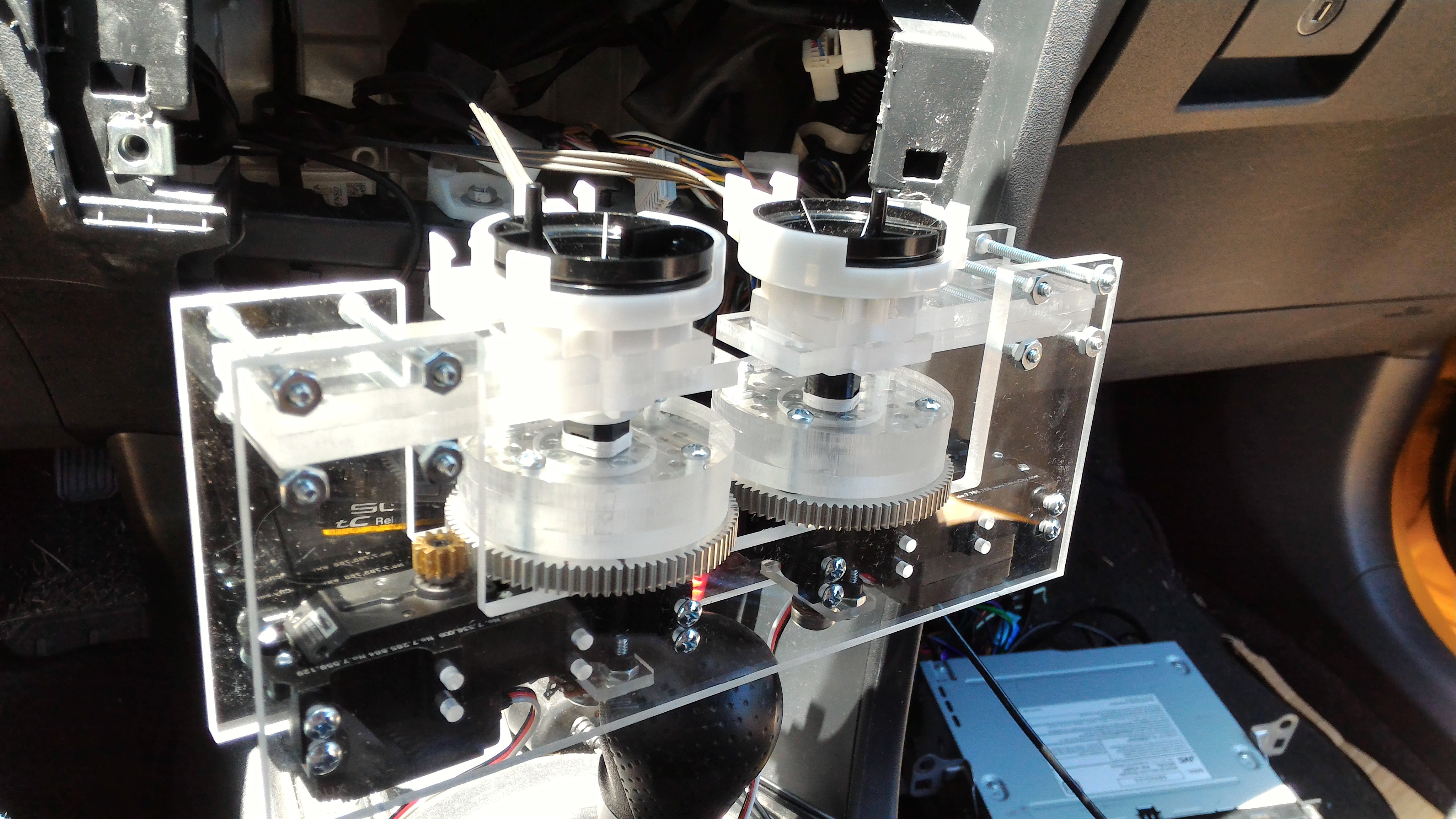
The one on the right shows the assembly before I stuffed it into the dash. The servos are mounted in "gearboxes" that give them 7:1 advantage. (https://www.sparkfun.com/products/12608) I think the servos could have turned the cable assembly without the gear reduction, but I didn't want to risk one of them burning out after the project is finished. The gear reduction makes it a little easier for the servo to achieve the desired position since I can program it so run at full power until it is very, very close to correct spot.
I used 1/4" acrylic for the brackets and (what I am calling) the adapter hubs.(The "adapter hubs" are screwed to the top of the big gear.) Why 1/4" acrylic? Because it's what was in my garage and my CNC router can cut it.
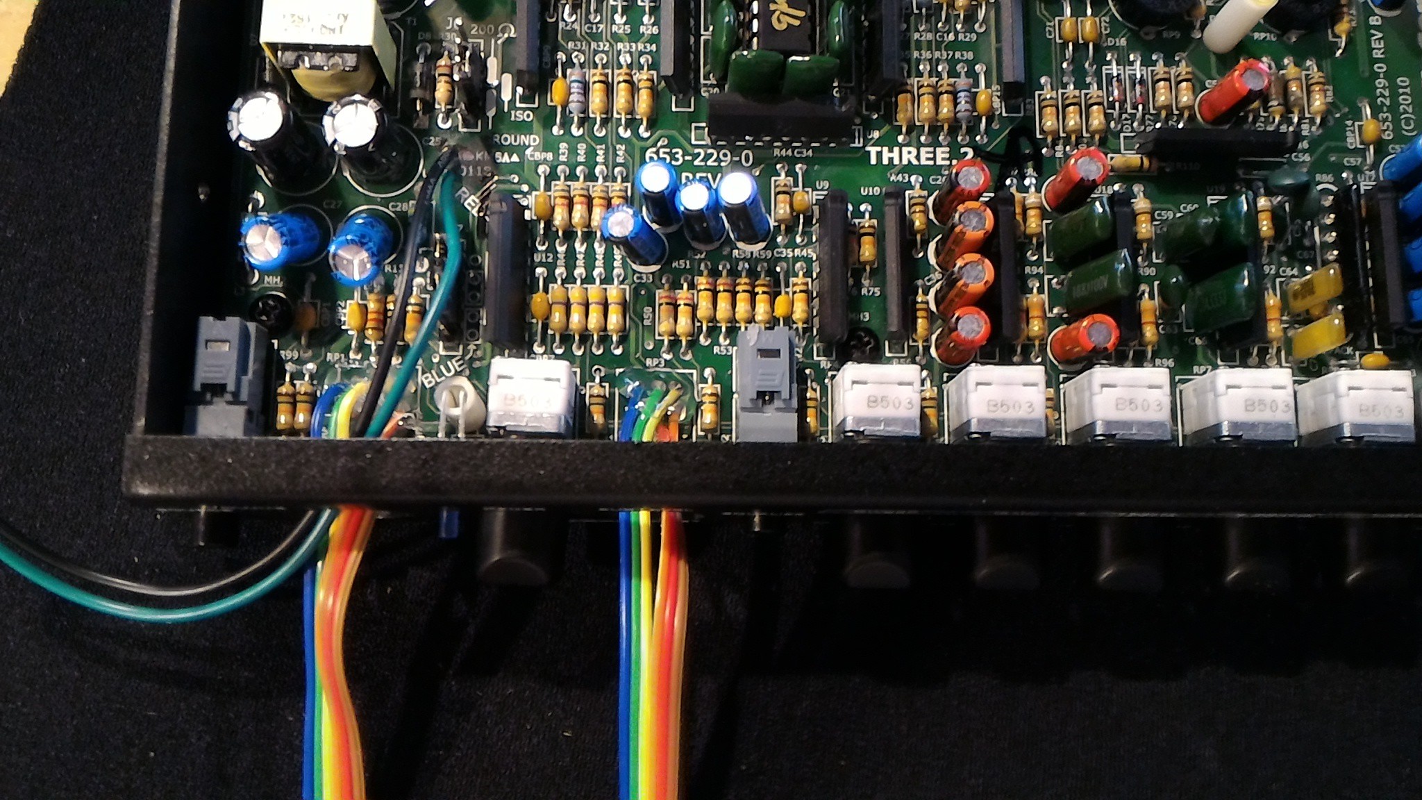
I've also made progress on some of the electronics. Right now I'm working on the EQ/Crossover/Line-driver that arrived a few days ago. It is an AudioControl Three.2, and it will take the output from the Schiit Modi and make it awesome. Actually, it is going to do exactly what it is meant to do. There is one thing about it that I have to modify though: volume knobs. This thing is going to be mounted inside the dash with no easy access but it will be my primary method of controlling the volume. To solve this problem, I am replacing the mechanical potentiometers with digital ones that are controlled via I2C (MCP45HV31).
Discussions
Become a Hackaday.io Member
Create an account to leave a comment. Already have an account? Log In.