 AndrewMcDan
After much debating with myself, I've decided to enter this project into TheHackadayPrize contest. One of the requirements for a project to be eligible is that the hack be connected somehow. Going back and reading my project description I realized that I left out the bit about remote starting the vehicle from any internet connected device and potentially being able to stream video from the car's camera and reading log data.The data connection in the Android device will help make this possible. I'll be posting more details as soon as I've had a chance to make some headway on that front.

In the meantime, how about some details about how I managed to make the new head unit (JVC JW-V50BT) work with the existing USB, auxiliary input, and microphone in my car? Starting with the easy stuff. The USB and auxiliary connections were fairly easy. It was just a matter of examining the wiring schematic for the car and making adapter cables. The microphone was a different story.
The new head unit came with a crappy little mic that they expect to be mounted on the dash with two-sided tape. But I figured that would be silly since my car came stock with a mic built into the dome-light assembly. Upon comparing the connections of the two mics, it was clearly apparent that this would definitely be more of a hack than an adaptation. To the right is the stock connector for the mic. The new mic had a 1/8 inch TS connector on it. The goal: hack a 2 conductor connection to work with a 5 conductor connection (actually 4, but there's 5 wires there).
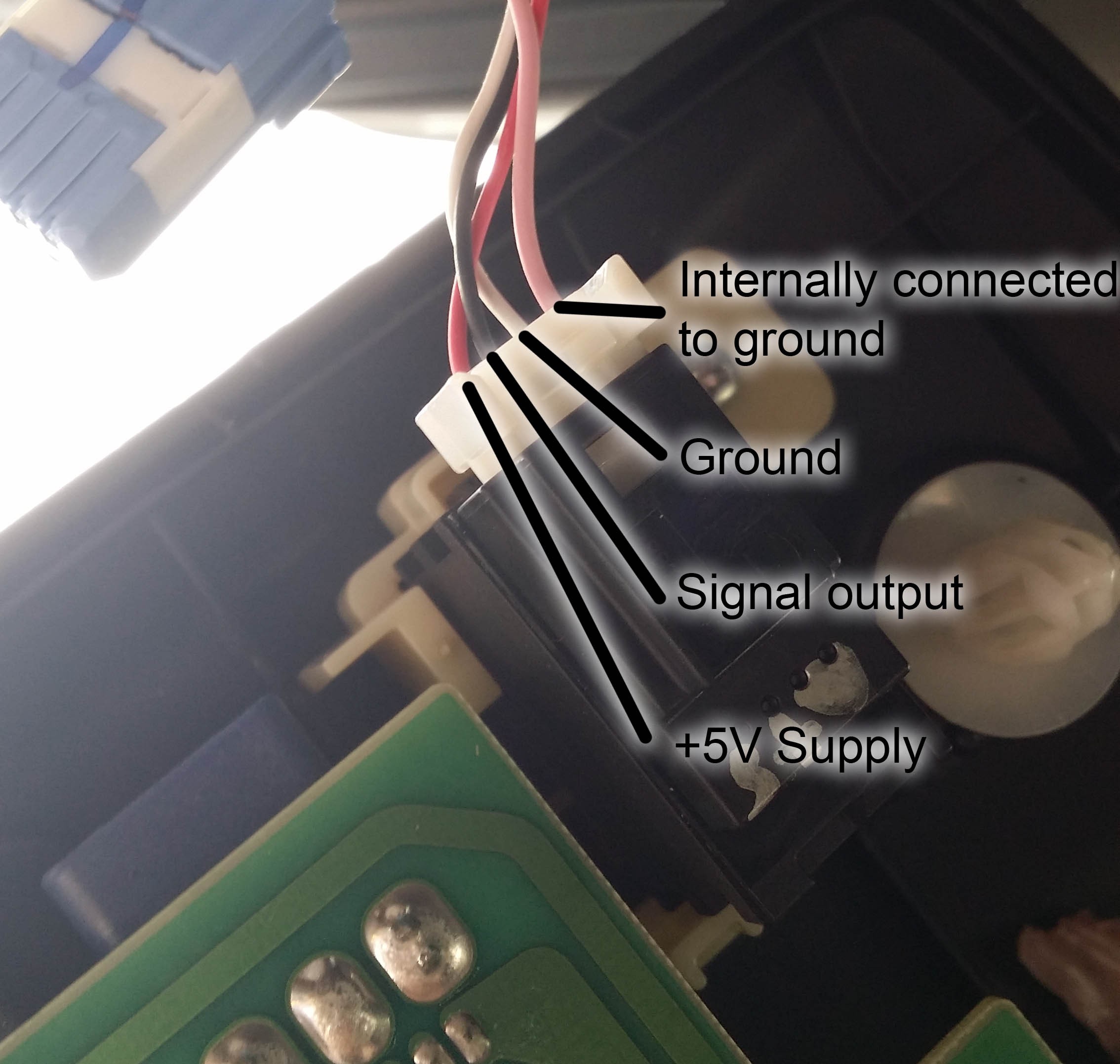
This is the connection to the microphone module. I took it apart (and forgot to take pictures) and figured out which wire served which function. I had done a bit of searching on the web to see if I could find anyone that had already sniffed out the functions of each of these wires and the best information I could find was that the microphone requires power. The schematic lists the connections to the mic module as SNS2 (pink), MCO+ (black), MCO- (white), and MACC (red). (The schematic also shows the shielding around the cable. That would be the gray wire.) Although I wasn't certain, I figured that they were, respectively, sense (for the stock head unit to detect the presence of the mic, Bluetooth in that head unit will not work without it), signal output positive, signal output negative, and accessory power.
This turned out to be pretty easy to confirm once I had a look at the PCB. The white and pink wires are both connected to the ground plane on the PCB inside the module. The 5 volt supply has an AC blocking capacitor near the connector. The positive side of the signal has a DC blocking capacitor near the connector. Knowing this information made it possible for me to work out a way to connect it to the new head unit.
Finding a 5 volt supply for the microphone wasn't too difficult since I've got a couple of spare USB cell phone chargers laying around. That was just a matter of splicing them together. The signal wire was a different story. First step was to figure out which side of the 1/8"TS connector was connected to ground. A simple multimeter/resistor combination made this trivially easy. Then on to connecting the two. Since the stock mic module has a built in pre-amp, I figured it would output a really hot signal. I hooked up my handy little DSO Nano o-scope to output of the stock mic and saw a nice waveform in sync with door chime. I noted that the peak voltage was about 100mV.
Then I hooked it up to the crappy mic that came with head unit and couldn't get any decent reading out of it. I tried talking directly into the mic, tapping it, holding it up to the speaker on my cell phone. It never registered any voltage. And this was with it connected to the head unit. What's more is that the head unit acted like the mic wasn't even plugged in. This was unsettling and very annoying.
So what is a good hacker to do? Well, pop open the brand new $400 head unit and poke around of course. Alas, in my poking around I found that the mic connects (almost) directly to the Bluetooth module inside the unit. The PCB with the 1/8" plug soldered to it had a short pair of wires (with JST connectors on either end) connecting it to the PCB with the Bluetooth module soldered to it. After tracing traces and I concluded that this pair of wires must carry the mic signal and I should hook directly to that. Knowing that most Bluetooth modules can't handle a hot signal on the mic input, I grabbed my soldering iron, a 1 meg-ohm resistor, a whole bag of 10k's and went to work.
Firstly, I had break to out the connection to the Bluetooth mic input so that I can get at it from outside the unit's case. A couple of sacrificial male jumper wires did the trick. Next, figure out how much attenuation the signal needed. I made a simple voltage divider using the 1M and a single 10k for my first try, and worked my way up to a 1M and 110k combination. This yielded the best sound quality and volume. Solder, heat-shrink, and done.
Overall, I am quite pleased with how the install went. The USB and AUX inputs work as expected. The head unit works great with the Galaxy S3, and as a bonus, it also works a a great monitor for any other HDMI source that can output 480P60, namely a GoPro. I think I might install my old GoPro so that it looks out the windshield and keeps a running video log (useful in the event of an accident).
Discussions
Become a Hackaday.io Member
Create an account to leave a comment. Already have an account? Log In.