 AndrewMcDan
I've made a fair amount of progress on the power supply for the various 5 volt and 3.3 volt components (Arduinos, tablet, etc.). This includes the battery for powering the remote start controller and the standby controller for lights.
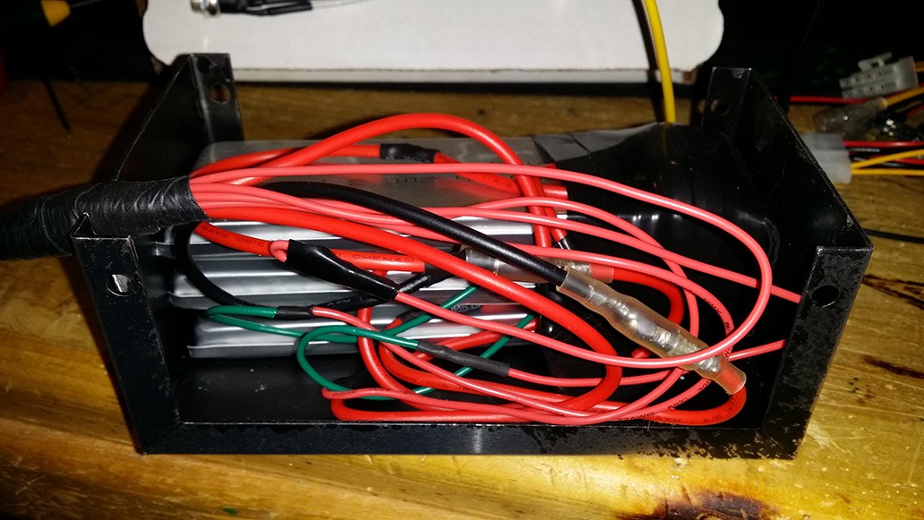

The battery pack is made of three Turnigy 5000mAh 1S 20C 3.7V Lipoly batteries connected in series to form a 5Ah 3S 11.1V pack. The battery pack is directly connected to a Mini-Box OpenUPS. The OpenUPS charges the battery pack and manages battery run time after the ignition has been switched off. Once the ignition is switched off, the battery powers certain devices for a preset amount of time before removing power from them (e.g. RasPi). The controllers that require battery power all the time will be connected directly to the battery pack through efficient DC-DC buck converters. I plan on building within the power supply a controller that monitors battery voltage, and in the event the battery voltage dips below safe voltage on any cell, it will completely disconnect the battery pack through latching relays. The OpenUPS feeds into a Mini-Box PicoPSU that outputs 12V, 5V, and 3.3V. This supplies all devices that require 3.3 volts and any device that requires a shutdown timer on 12 volts or 5 volts.
For devices that do not require a shutdown timer but are not high power devices, 5V and 12V will be provided using a pair of Mini-Box DC-DC USB 200 power supplies. This provides plenty of power for all the microcontrollers and the handful of 12V devices that require regulated voltage (camera, DVR). More photos and details to come.
Discussions
Become a Hackaday.io Member
Create an account to leave a comment. Already have an account? Log In.