 AndrewMcDan
After getting the RN-52 module hooked up to a USB/serial cable and getting the module configured and paired with my phone, I connected my logic analyzer to the digital audio output. It took me an embarrassingly long time to figure out that the silkscreen on the breakout board was incorrect and that I was trying to monitor output from a input line (I should have just read the product description on Sparkfun's website). But, silly mistakes notwithstanding, I did manage to get data out of the device and it appears to output good I2S data.
While digging through the datasheet for specifics on how to configure the device, I found that it is capable of outputting S/PDIF. I set the module to output S/PDIF and connected it to my A/V receiver. It works great as a Bluetooth A2DP to S/PDIF adapter. (I might re-purpose it for that.)
After listening to a few songs and playing with software control of pause/play/next/prev, I started digging through the datasheet and command reference to try to figure out how to get track/artist information from the Bluetooth source. Lo and behold, the RN-52 is not capable of retrieving that information. I should have figured that out long ago, but I was skimming the datasheets like an idiot. And so, I have to figure out a new way to handle audio.
My current idea on how to do this is to use the existing head unit since it has all the Bluetooth capabilities I'm looking for, it already has the circuitry/interfaces for the microphone and steering-wheel controls, and it has a built-in amplifier. That's a few less things to figure out. The plan is to offset the head unit back a few inches into the dash and mount the tablet in front of it. I'm considering eliminating all of the parts of the head unit that do not contribute to producing sound from either Bluetooth or line-in. That would leave me with only a single PCB (with two small daughter boards) to mount behind the tablet.
The one big question is how to communicate with the head unit to get track/artist info and send commands (play/pause/next/prev, answer call, volume, etc.). I poked around the innards of the unit a bit and found a few interesting things. Bluetooth is implemented using a BT module much like the RN-52. It's soldered to the main PCB in the head unit, and most of the useful data lines have bare solder test points that are easily soldered to. These data lines include AVRCP control lines over ASYNC serial and PCM I2S signals.
The test points are on the bottom on the PCB. This is the top side showing the Bluetooth module. It's worth noting that this module does not have a built-in antenna as the RN-52 does. There is a U.FL connector nearby for the antenna that is mounted in the front panel.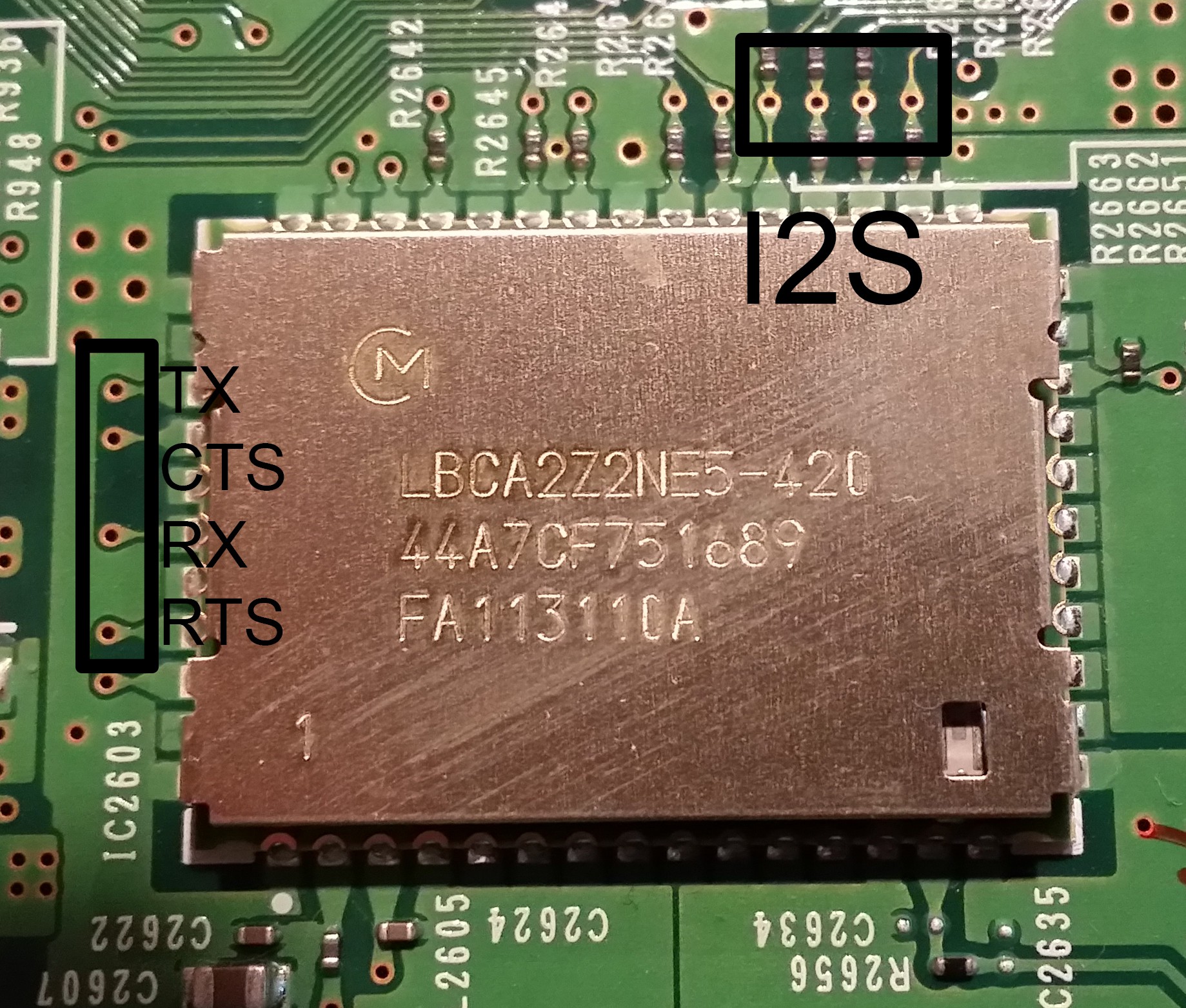
Here is the bottom side of the PCB.
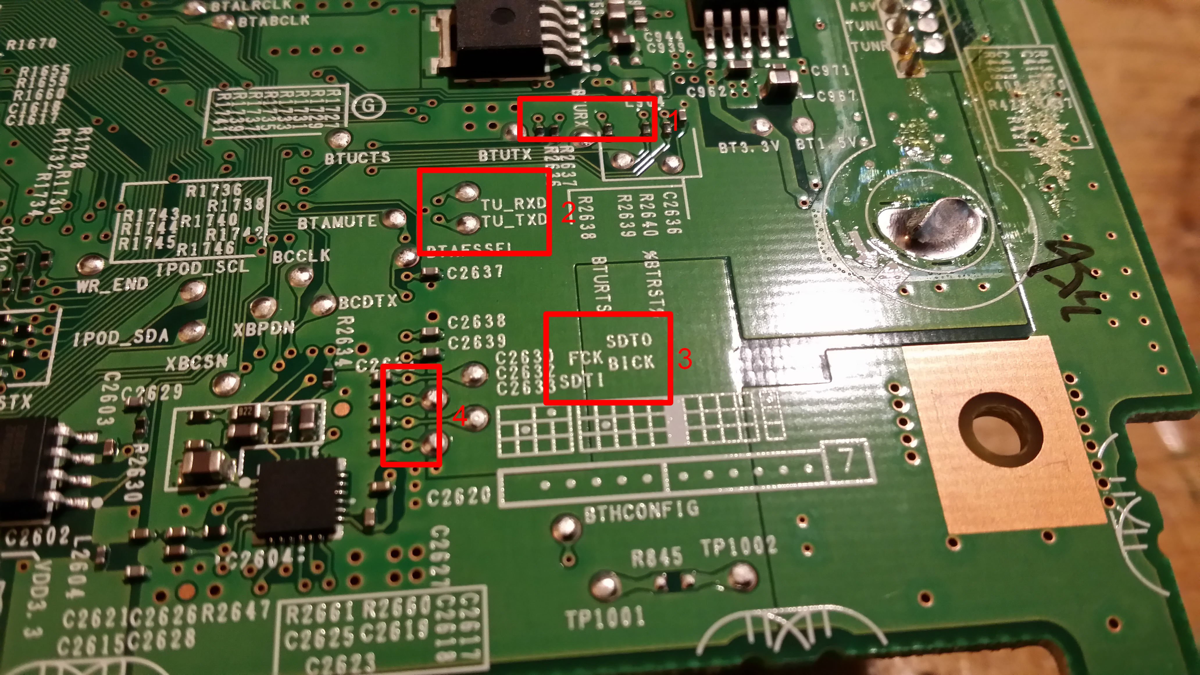
Box 1 is the UART that I found AVRCP data on. The track info is tranferred as normal ASCII data. Box 2 shows what appears to be a UART but I wasn't able to get anything useful from it. The silkscreen in box 3 tipped me off to the possibility of there being I2S data lines there. I recorded a little bit of data from the for points in box 4 and it appears to be valid I2S. It would make sense becuase most CD players use I2S to transfer audio data around. You can also see some silkscreen that implies some other functions can be hacked into with little work.
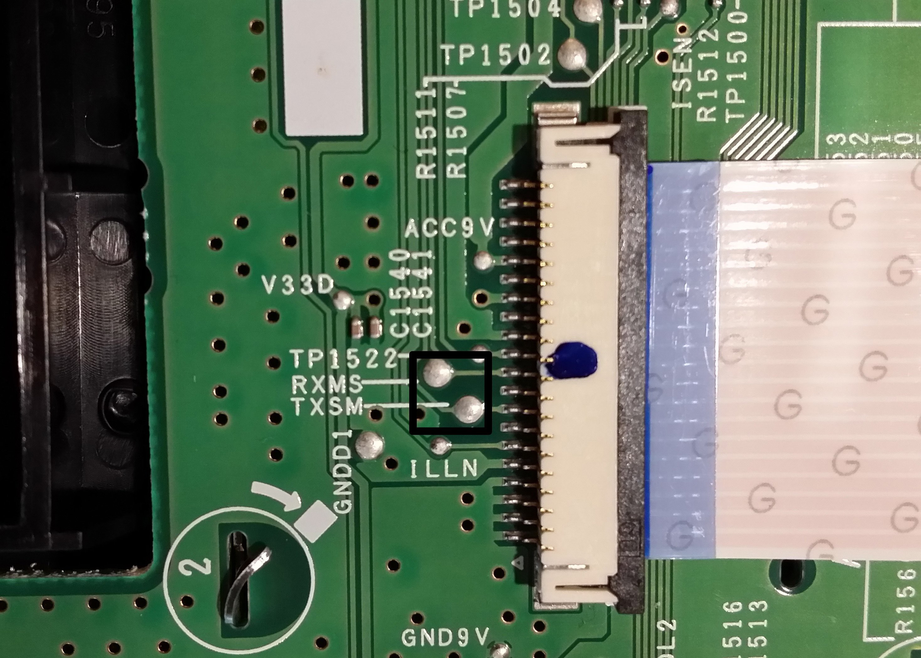
The front panel of the unit connected to the main PCB with a single ribbon cable. It has its own µC that seems to interface everything on the front panel to the main board. In the picture below you can see the RX/TX lines that I ended up getting data from.
When I connected the logic analyzer to it, I assumed that it would be communicating using standard 8N1 ASYNC. But all of the data I captured had framing errors. My initial thought was that the two controllers were communicating with 10 bits instead of 8, but this only helped about half the framing errors. Not to mention, the data the analyzer came up with seemed random. After fiddling with the analyzer settings for a while I finally came across the proper setting: 8E1. That's 8 data bits, even parity, and 1 stop bit. This is the first time I've ever seen parity used, and I almost gave up before figuring it out.
I reversed engineered part of the communications protocol used by the front panel µC, specifically the part for track info. It seems straightforward enough. You can see my efforts here: Google Spreadsheet. Be warned, the spreadsheet contains conditional formatting that makes it run a little slow in the browser. "Sheet1" breaks down the captured data into blocks for each time the track info changes. "Sheet2" and "3untitled" have the full data-sets for each of the UART channels.
Here's a shot of the head unit with the top removed, along with the CD player and heatsink. The front panel is laying flat. The black rectangles show where the photos above highlight.
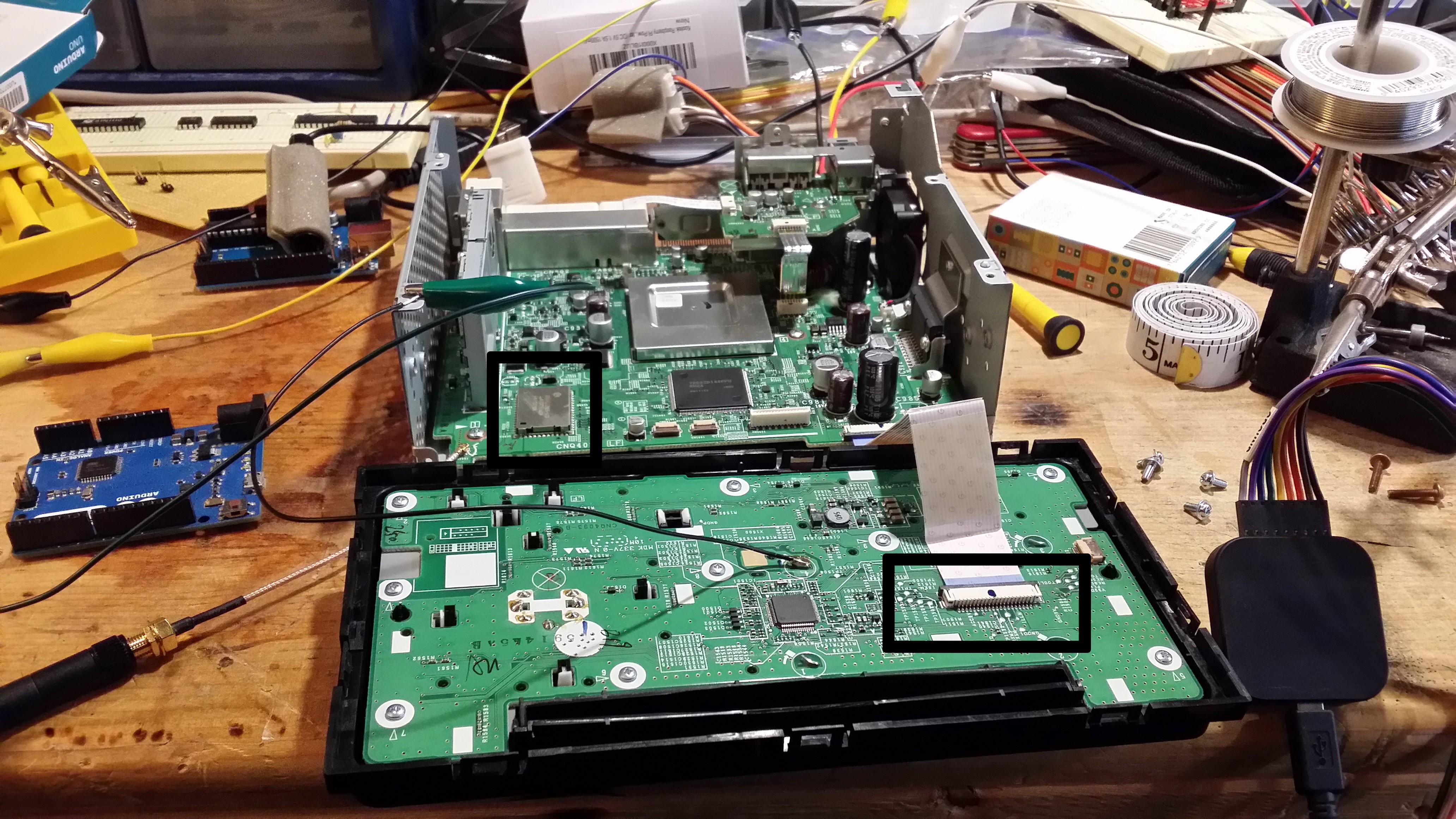
You may not be able to tell it from the photo, but when the unit is fully assembled, there is a whole bunch of wasted space inside. Enough space that if I leave the entire unit in the car, I can probably mount a µC inside the unit. I'll have to program a µC that lets me communicate with the unit over IP so that it can be integrated with the rest of my car PC system. If I can mount it inside the unit and expose only a RJ45 plug (for Ethernet) then I won't have to worry too much about electrical noise and interference.
I found that the unit works just fine without the CD player installed. If it will work without the front panel, or if I can spoof the existence of it, I might be able to get away with using only the main PCB. This would allow me to mount it nearly anywhere since I would be able to built an enclosure for it. If I can completely emulate the front panel with a µC, and just relay messages between the tablet and the main PCB, then I would be able to still use the line-in, USB, and tuner capabilities of the unit. This will be my ultimate goal, however, I won't consider the project a failure if I can't managed it.
One last thing to note: because the Bluetooth radio has an external antenna with a U.FL connector, I think I will be using a full-sized 2.4GHz antenna in the final build. You can see in the photo that I had it set up that way for testing.
My next update will likely be my experiences with the Wolfson Audio chip. Since I can get at I2S data, I might as well bring that data out to a S/PDIF connection on the back of the unit. The final design may even use my original idea of transmitting audio to the amplifiers over optics.
Discussions
Become a Hackaday.io Member
Create an account to leave a comment. Already have an account? Log In.