 ehunck
Assembling the PCBs
A while back I ordered several PCBs and two DWM1001 modules for testing and evaluating. I have linked the designs for the PCBs in GitHub, but I wanted to update what I had to do to get the boards working.
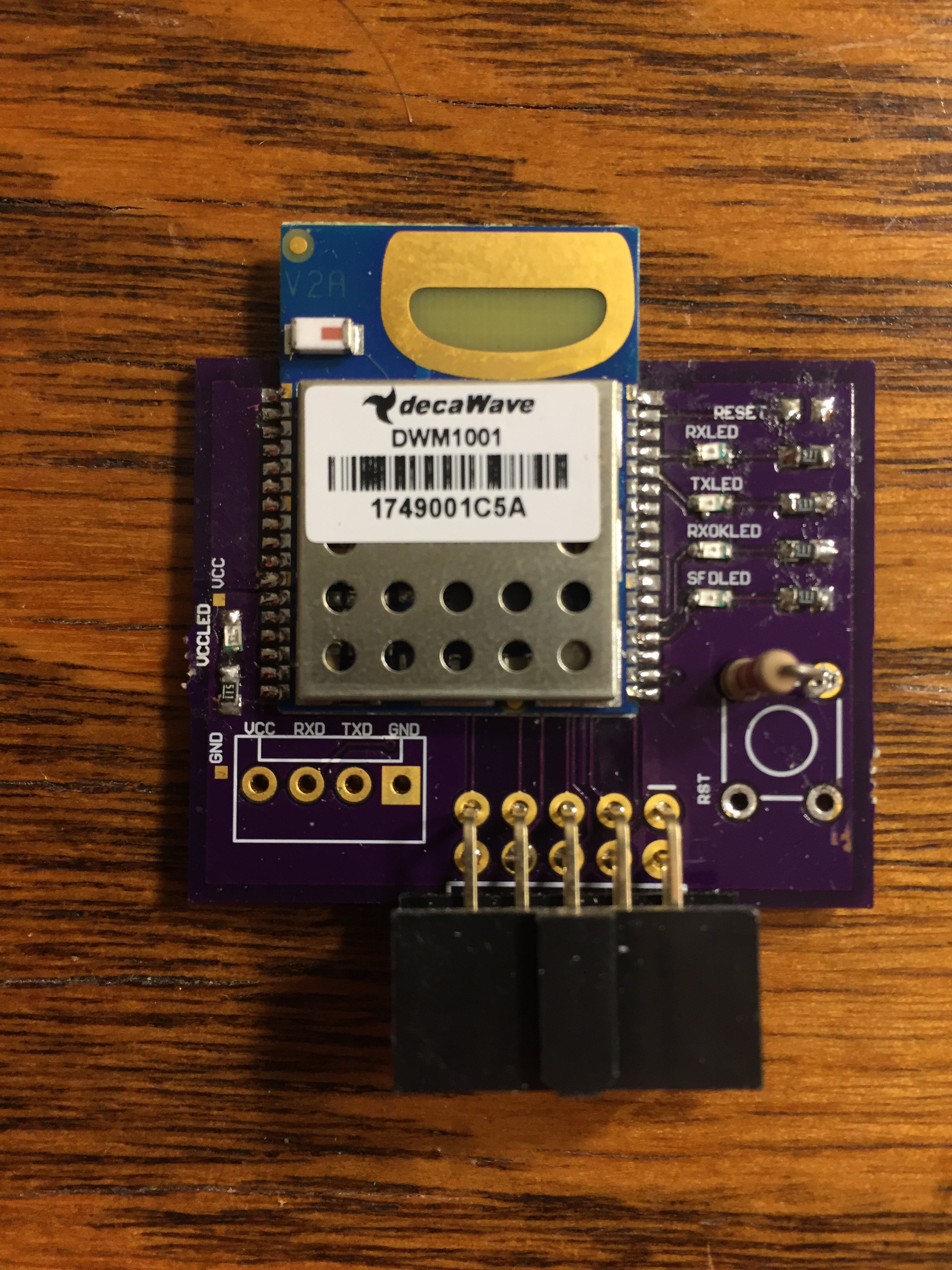
First I hand-soldered the components to the PCB. I found an error with the default signal level of the RESET pin which I fixed by excluding the push button and putting a pull-up resistor in its place there.
This board has a 10 pin right-angled connector on it, because it is intended to be mounted upright so there is an even radiation pattern around the device.
Connecting to the module via UART
The connections to this device are rather simple. Power the device with 3v3 and connect TX, RX, and GND to a USB to TTL Serial converter.
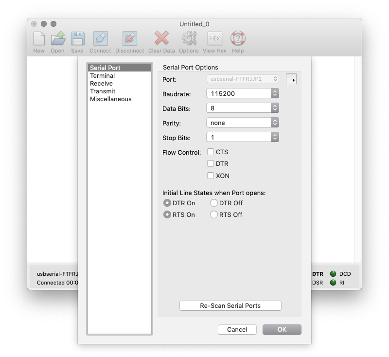
I then use an application like CoolTerm to connect to the device. The DWM1001 has a shell interface that can be useful for testing. The settings for connecting to the device can be seen below.
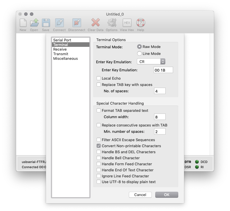
The ones that I want to highlight are a baud rate of 115200 and line endings being CR.
To enter the shell, all you have to do is send 0x0D twice to the device. This is the same as sending two CR line endings. So, once I connect to the device in CoolTerm, I click in the window and press "return" twice. This causes the DWM1001 to go into the shell mode and respond with the following interface.
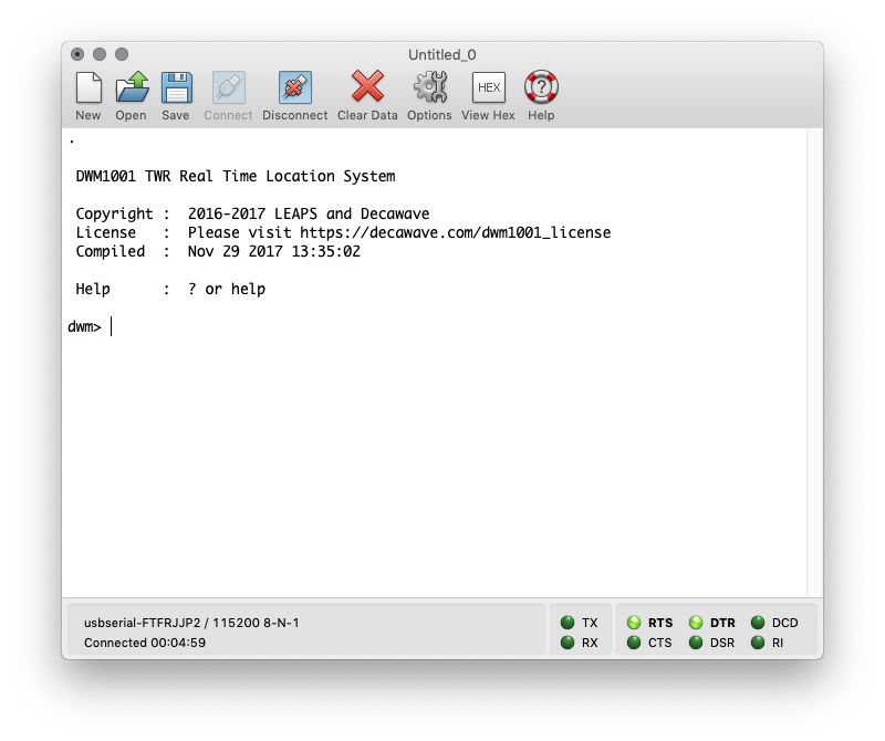
We're now into the DWM1001 shell interface and can now start experimenting with these devices.
Discussions
Become a Hackaday.io Member
Create an account to leave a comment. Already have an account? Log In.
Hello, what firmware do you use? Why do I use the "USB to TLL" module to connect the serial port of "DMW1001", but I can't get into the shell interface?
Are you sure? yes | no