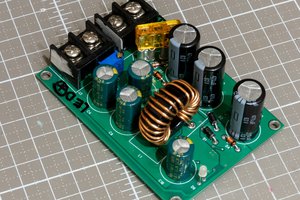
This is a simple power supply that can deliver 600ma of current from 1.5 volts to about 20 volts. It has current limiting and current limit indicators. The circuit is designed to be powered by a wall wart. The main components are two LM317, an op amp, a 12 volt regulator and some passive components.
The circuit uses one LM317 for current limiting and the second LM317 for voltage setting. Current limiting is accomplished using a six position rotary switch and the voltage is set using two pots one for coarse and the other for fine adjustment. The op amp is used to illuminate two leds, one for constant current (CC) the other for constant voltage (CV). I chose to use a common cathode RGB led. The 12 volt regulator provides a fixed voltage source for the ammeter, voltmeter and fan.
The LM317 is a good voltage regulator and is used in many commercial products. It is easy to work with requiring only two resistors to set the output voltage. As a variable current regulator it is not as easy to work with. The regulator maintains a maximum of 1.25v between the output and adjust terminals. When the voltage between these terminals reaches 1.25v the regulator reduces the output voltage to maintain this maximum voltage differential.
As a voltage regulator (U2) we use a resistor divider (R8 and RV1+RV2) to allow a fraction of the output voltage to return to the adjust pin. By adjusting the ratio (R8 and RV1+RV2) we change the output voltage.
Current limiting is accomplished by sensing the voltage drop across a shunt resistor (R1 through R7). By changing the value of the shunt we change the amount of current that U1 will allow to flow before it begins to limit.
For example lets use a 1 ohm shunt. The LM317 regulator will begin limiting when the voltage drop across the resistor is 1.25v. Using Ohm's Law we see that the current draw will be 1200ma when a voltage drop of 1.25v occurs across a 1 ohm resistor (I = V \ R) or ( I = 1.25v \ 1 ) I is 1.25A or 1250ma. When we have a shunt with a resistance of 10 ohms a current draw of 120ma will give us a 1.25V drop across the shunt (I = V \ R) or ( I = 1.25v \ 10 ) I is .12A or 120ma output.
A potentiometer would make an ideal shunt for this circuit but the value we would need is hard to find. We would need a 2 watt pot with a range of 1 to 150 ohms and an anti log taper. So I chose to use a rotary switch with six ranges for simplicity.
The op amp functions as a comparator, providing CC and CV indication. The op amp compares a fraction (2/3) of the input voltage to the output voltage of U1. The divider R12 and R13 determines this fraction. If 2/3 of the input voltage is less than the output of U1 then U1 is not limiting the current and the green led lights. If 2/3 of the input is greater than the output of U1 then U1 is current limiting and the red led lights. Remember that there is a voltage loss in U1 and a voltage loss across the shunt so 2/3 of the input will only be a volt or two below the output. I designed the circuit to use a common cathode RGB led. It will toggle colors when the circuit limits. The op amp is not critical the LM358, TL072 are pin compatible and will work just as well.
The circuit is intended to be powered by an ungrounded wall wart that can provide about 24volts at 1000ma. I have built two of these circuits so that I can connect them in series to provide both positive and negative voltages. If you want to do the same you must have a SEPARATE power source for each circuit THAT IS NOT GROUND REFERENCED OR YOU WILL CREATE A SHORT CIRCUIT. If you are unsure as to what this means please take the time to look this up and understand it thoroughly before you join any power supplies together (series or parallel) . I can absolutely guarantee bad things will happen if you don't. This also applies to oscilloscopes which are "earth" or ground referenced.
Heatsinking is also a great concern. The regulator will draw an input current equal to your output current regardless of voltage. The regulator...
Read more » w_k_fay
 MagicWolfi

 Kevin LO
 Marc-O.