 matthewreed
Why hydroponics?
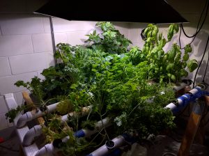
As the world population continues to grow and become increasingly connected, more attention is being focused on the disparity in living conditions across the globe. The further technology advances, the harder it is to believe that people in many parts of the world still struggle with attaining basic human necessities such as access to clean water and sustainable nutrition, and yet these issues remain unresolved. Addressing these problems will require collaboration from the global community, and I believe that hydroponics has the potential to be at least one part of the solution. Let’s look at the reasons why hydroponic gardening is superior to traditional agricultural methods.
- Hydroponics requires less space than traditional gardens when taking advantage of vertical space by stacking growing systems on top of each other.
- By tweaking the environment and nutrients given to the plants in real-time, hydroponics can speed up the process of growing plants by as much as 50% [1].
- Because the system is closed-loop, hydroponics can also use up to 90% less water than traditional farming methods [2].
- Plants can be grown year-round, increasing space utilization in the winter months.
- The absence of dirt means produce is cleaner, and the clean environment means less bugs to damage the crop and no weeds to worry about.
- With greater control over the nutrients being fed to the plants, they can be grown to contain more vitamins and minerals as well as improved taste.
The biggest downside to hydroponic gardening is the cost and complexity of the system required to support it – and that’s where HydroBot comes in.
The HydroBot Vision
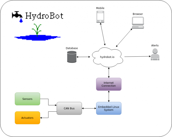
HydroBot looks to solve the problem of controlling a complex hydroponic system through automation, simple interfaces, and flexible design. Automation will be accomplished through the use of an embedded computer that will handle all the feedback control loops and scheduled tasks. The embedded computer will communicate with a server to provide data logging and an easily accessible remote interface. The server will also host a webpage with data graphs and user controls, and have to ability to send out critical system alerts. To make the system flexible, a modular architecture will be used for all functions that interact with the physical world, such as sensors and actuators. Each function will have a corresponding module to carry out that specific task and report back to the embedded computer, which will act as a central hub for these modules. A multi-drop communication network will be used to connect the modules to each other and to the central hub. A block diagram of this system architecture can be found below.
Implementation Details
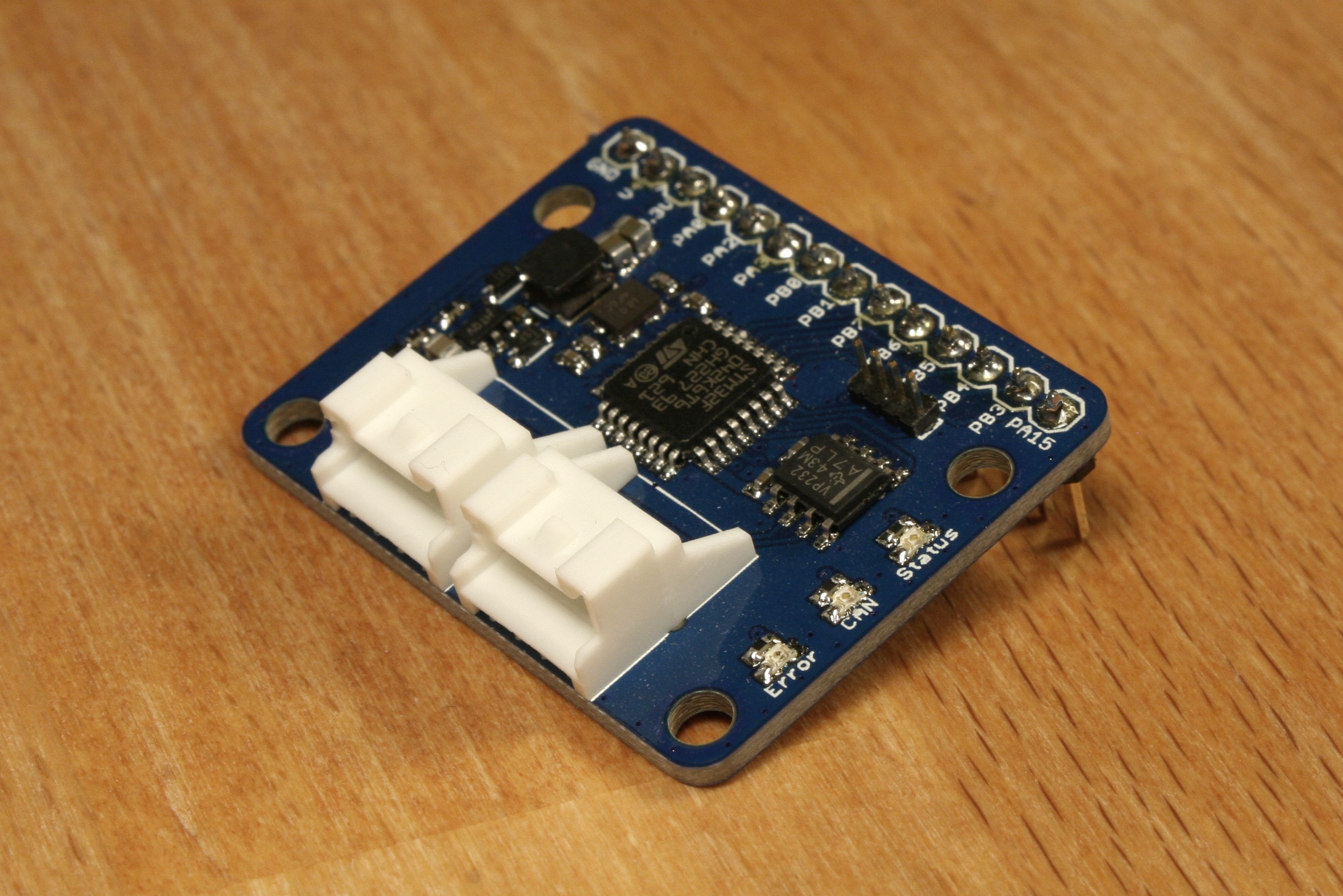
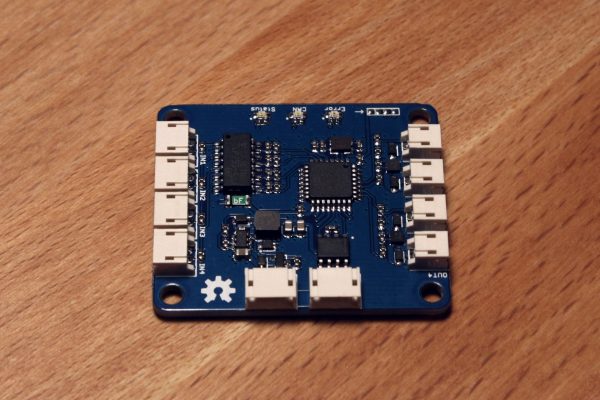
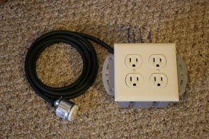
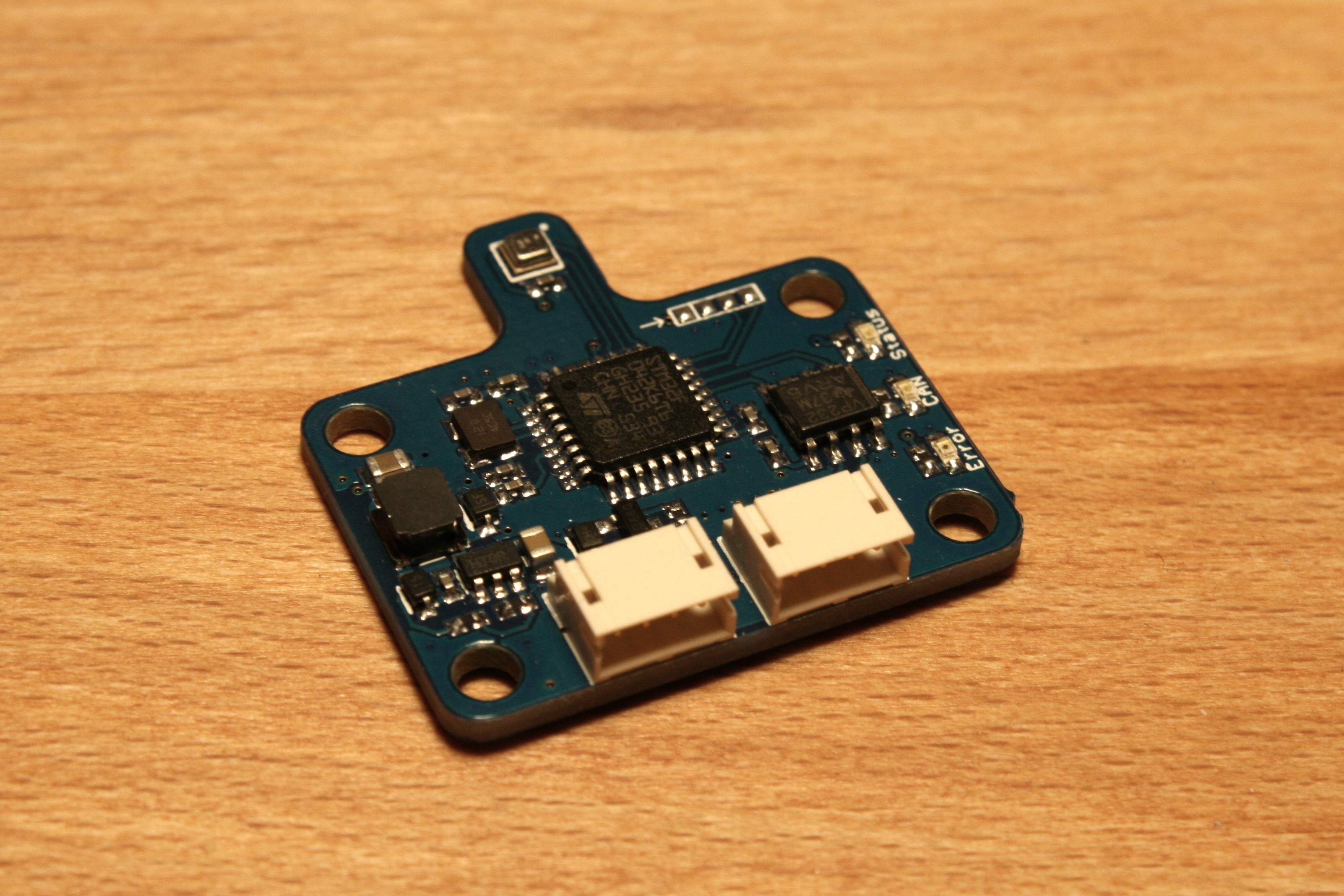
Although each module will be developed separately as the need arises, there are some high level system design decisions that will dictate the requirements for the modules. CAN has been chosen as the primary communication network for HydroBot, because it meets the multi-drop requirement, works well over relatively long distances, is very robust to environmental noise, handles errors gracefully, and has built-in arbitration and message priority. Support for additional communication protocols may be added in the future as needed – for instance, if an application requires wireless communication. To make the system as flexible as possible in a variety of applications, both 12V and 24V power will be supported. Modules will also be daisy-chain-able and allow up to 1A of pass-through current. To keep connectors consistent, JST ZH series has been chosen for module connections when possible. To keep a consistent code base and shared libraries across modules, STM32 microcontrollers will be used as the standard for module processing.
Several key modules have been identified to fulfill the basic functions required in most hydroponic systems:
- Environmental sensor to monitor air temperature, humidity, and pressure
- Water reservoir sensor to monitor water level and temperature
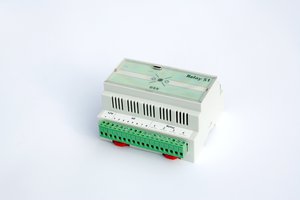
- Relay...
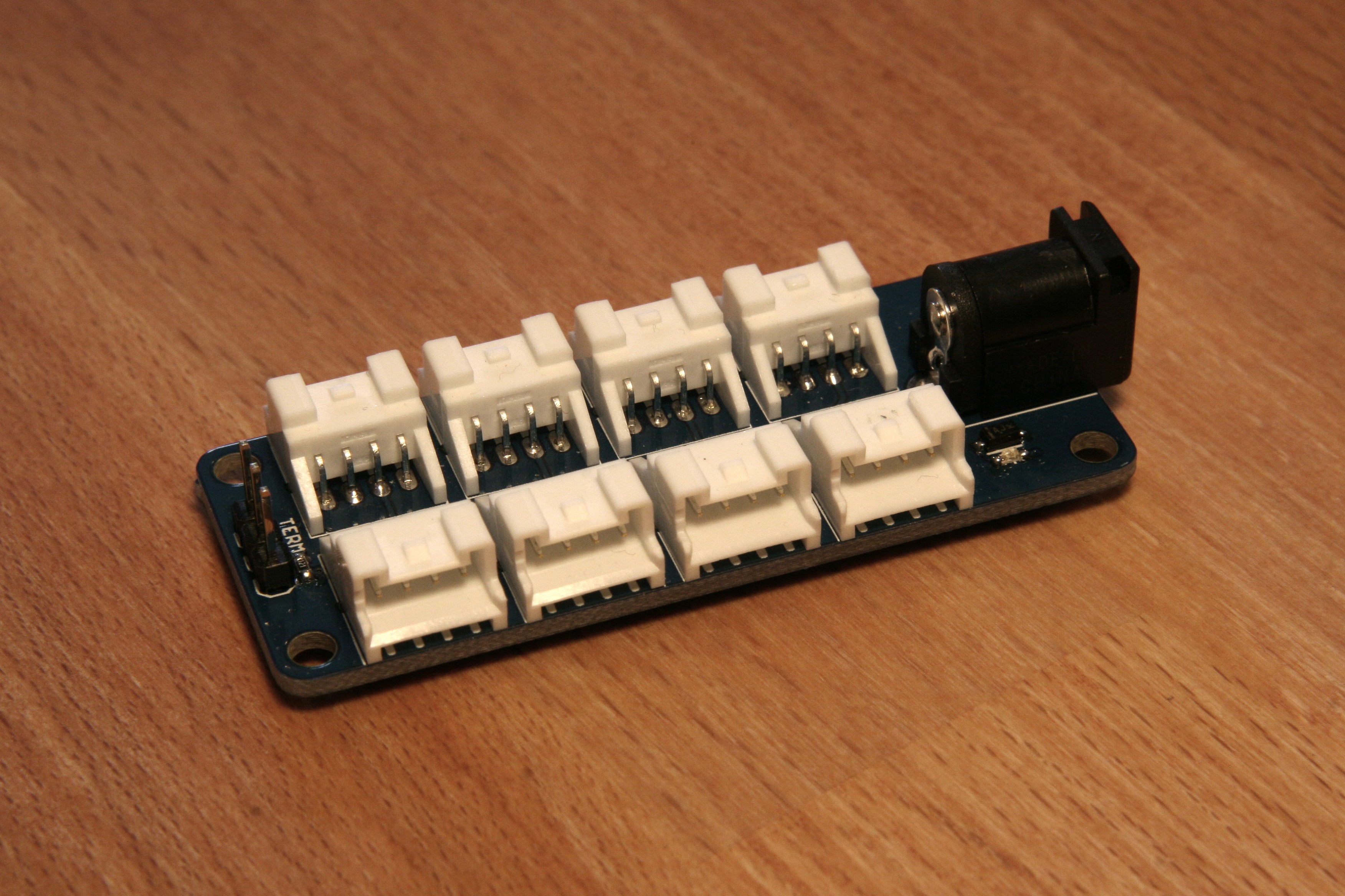 HydroHub is a
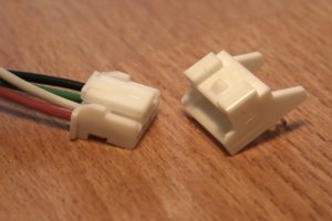
 strange.rand
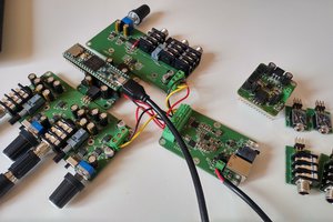
 Michele Perla
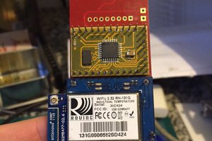
 E. N. Hering
 Ali Shtarbanov