 Scott Clandinin
In the future I will try to add instructions for this, but in the meanwhile I will cover the circuitry here. There are big improvements to be made to the hardware and mounting, but my methods worked well enough to be able to quickly throw something together.
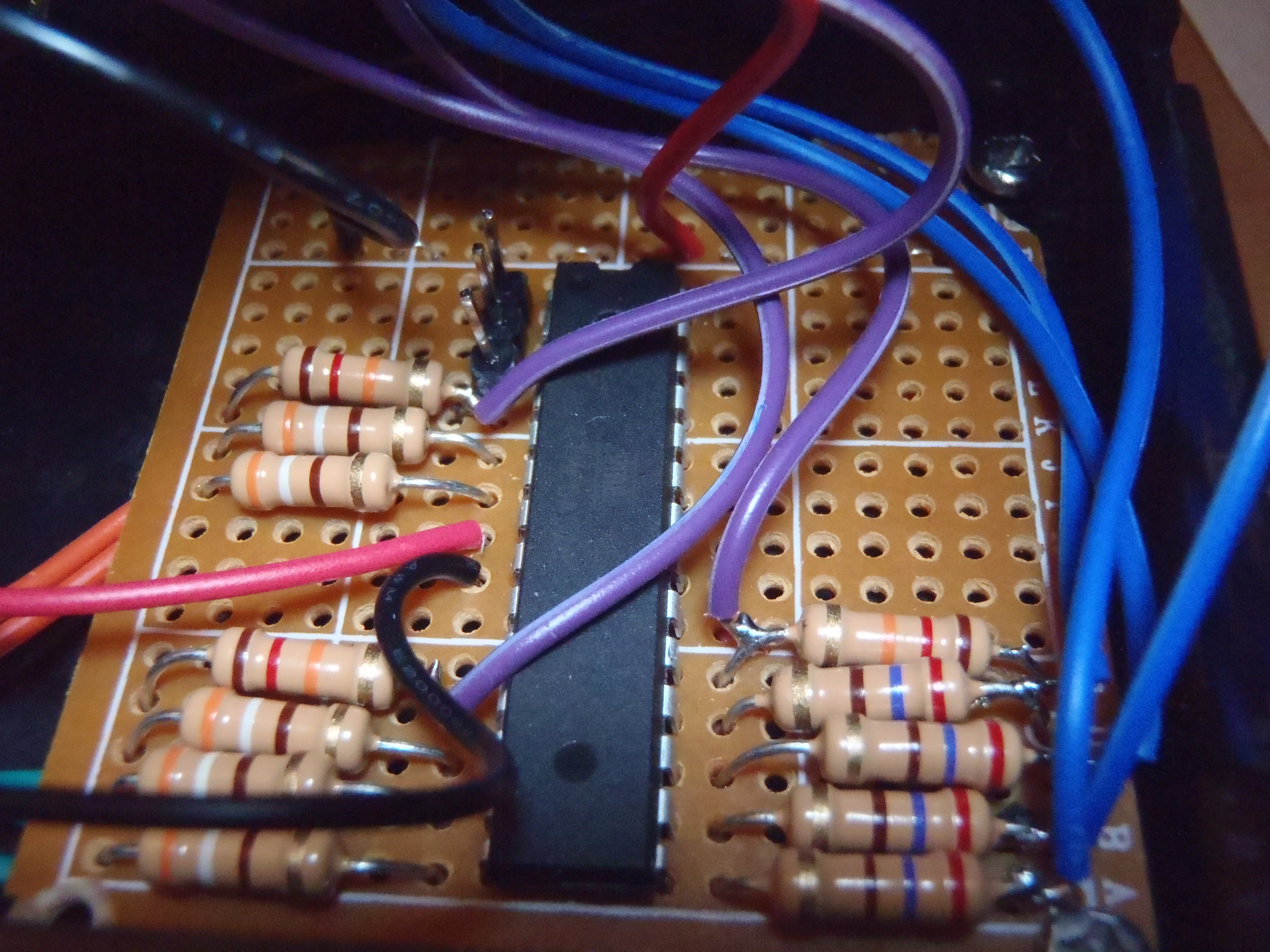
Circuit Top
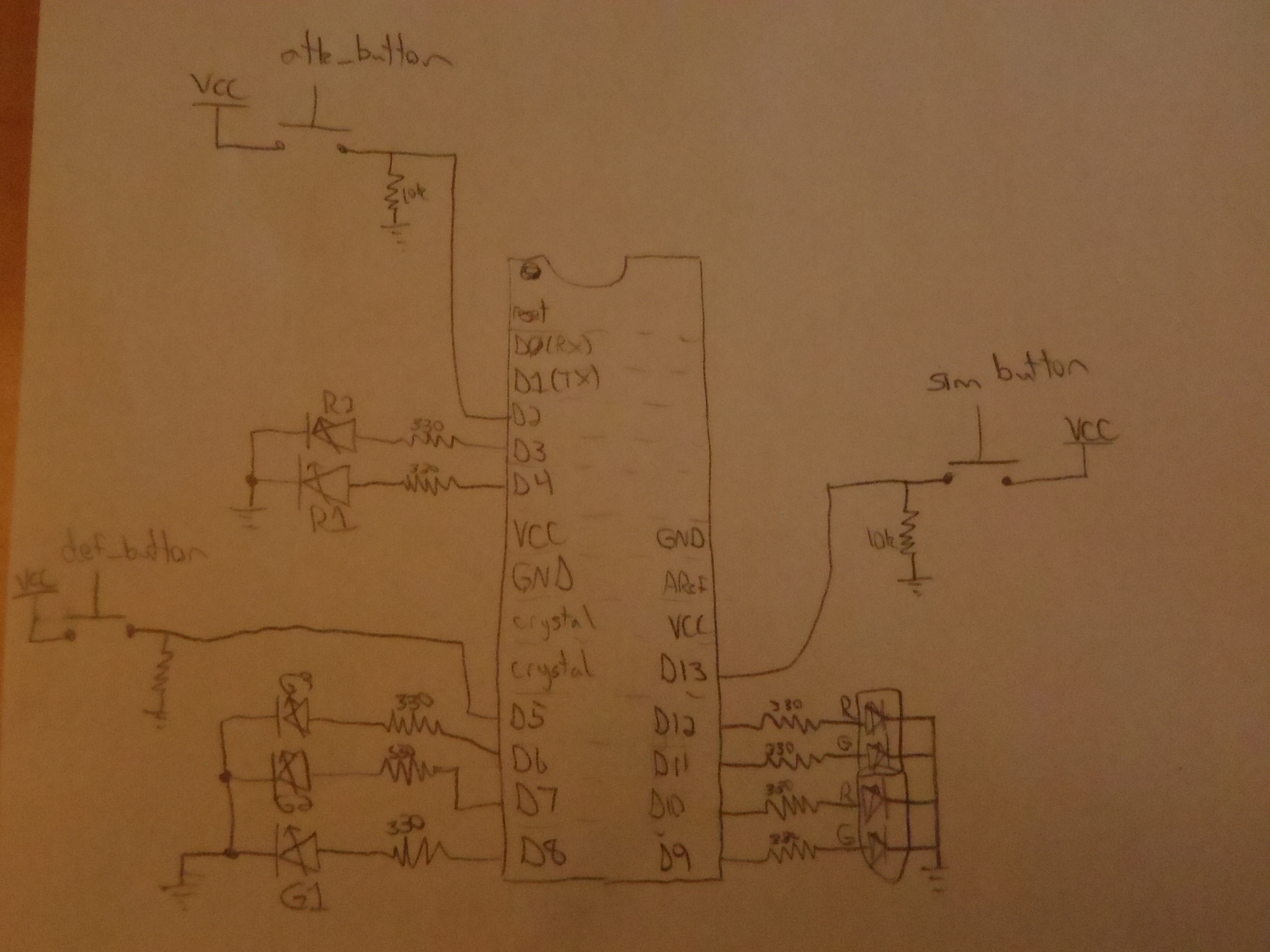
Since I'm lazy, and 10k and 330 ohm resistors always get used up, I chose resistors near to those values. I can get away with this because the value of these is not crucial. We'll pretend they are the right values! The 10k resistors are pull down resistors, and the 330 ohm just set the LED current. At the top left of the micro you can see the 3 header pins I added in for easy programming. Those pins are reset, tx, and rx.
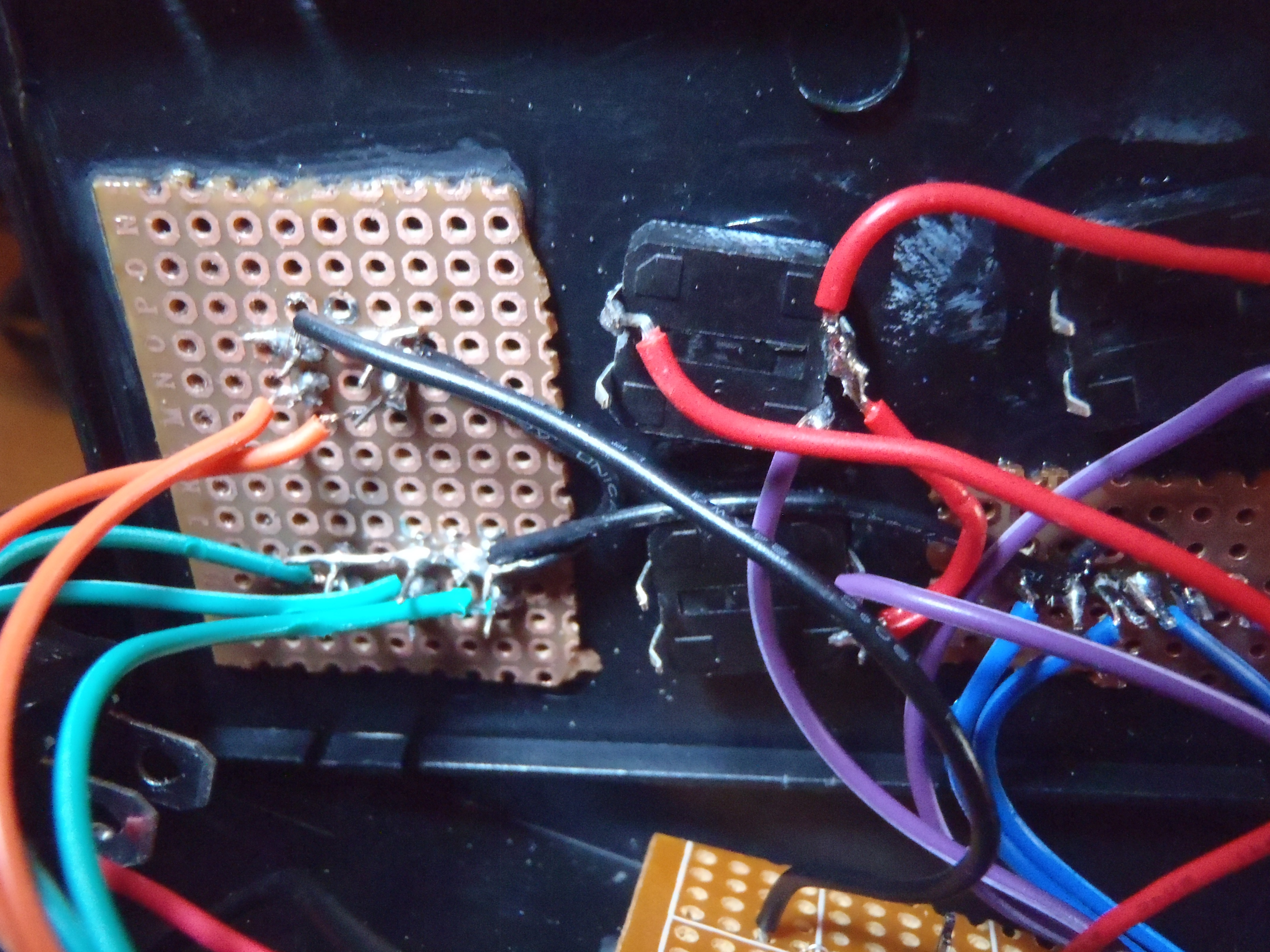
Circuit Bottom

Lid Top
I used super glue and protoboard to get the LEDs and buttons in place. You can tell I really hacked this together. Not the best way to do it, but it works for a proof-of-concept device. Super glue and buttons definitely don't play nice. I ruined a few buttons with glue leaking in, but eventually got it right. The button contacts suffered a bit regardless, but since all I needed way to establish a low-to-high transition, it was good enough.
Here is the link to the case I used. Great price too.
Discussions
Become a Hackaday.io Member
Create an account to leave a comment. Already have an account? Log In.