-
The finishing touches
07/29/2016 at 19:06 • 0 commentsMy button caps arrived and I was finally ready to finish off the project and make a video for it.
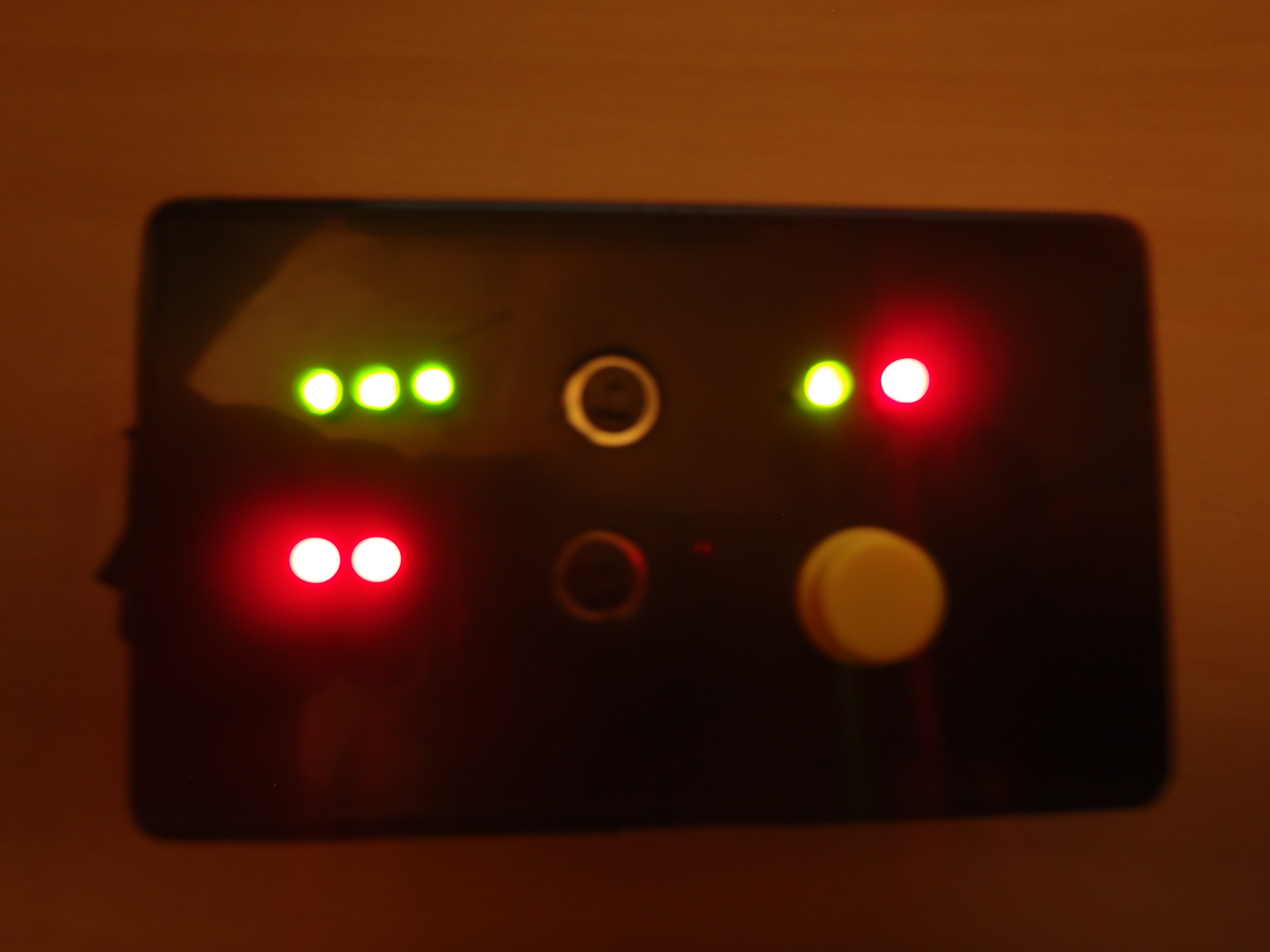
The hardware implementation was a bit rushed and not totally thought-out. This can be seen by the lack of symmetry in where I drilled in the button holes. I must have shifted things when I was tracing on the stencil I made. Thing don't line up as I imagined.
If I were to make it again, the first thing I would do is use a circular rocker switch rather than a rectangular one. I only really had a drill and dremel tool at my disposal, so cutting out the hole for the switch was a real hack job. I ended up covering the sides of the switch with electrical tape to hide the horrible cut. With a step bit and a drill however, it's easy to cut out the perfect hole every time, and that would have improved the aesthetics.
A future revision of the device could see the battery pack held inside the case itself to shrink the size. But that would require better planning and actual PCB with surface mount components and tighter cable routing.
Despite it's minor flaws, I'm pretty happy with how it turned out, and look forward to trying it out in a real game of Risk.
-
Serial Logs and the Wait for Buttons
07/12/2016 at 02:04 • 0 commentsBefore I take a video of the operation of this device, I am waiting for some button caps to arrive. In the meanwhile, I figured I would show you how I know the device is operating as expected.
![]()
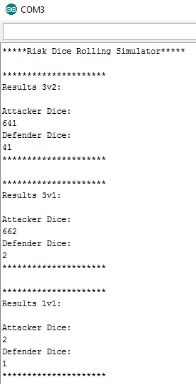
This is an example of a few different simulations through the serial monitor. I print out the dice numbers for each side, as well as the simulated dice in order from largest to smallest.
In the first result the defender lost two troops, as the attackers 6 beats the defenders 4, and the attackers 4 beats the defenders 1.
The video I will be releasing soon will include live serial monitor debugging with the simulation results to show that results shown by the LED's are indeed correct.
I'm also thinking about how labels would look explaining the meaning of the different LED's and buttons. However, it may be good enough as it is since it is mostly intuitive. The only thing that isn't totally clear is what the simulation LED's stand for. And of course on this device, the simulation LED's represent which side lost how many troops.
So now I just wait for those button caps to arrive!
-
Designing and Implementing the Circuit
07/08/2016 at 23:16 • 0 commentsIn the future I will try to add instructions for this, but in the meanwhile I will cover the circuitry here. There are big improvements to be made to the hardware and mounting, but my methods worked well enough to be able to quickly throw something together.
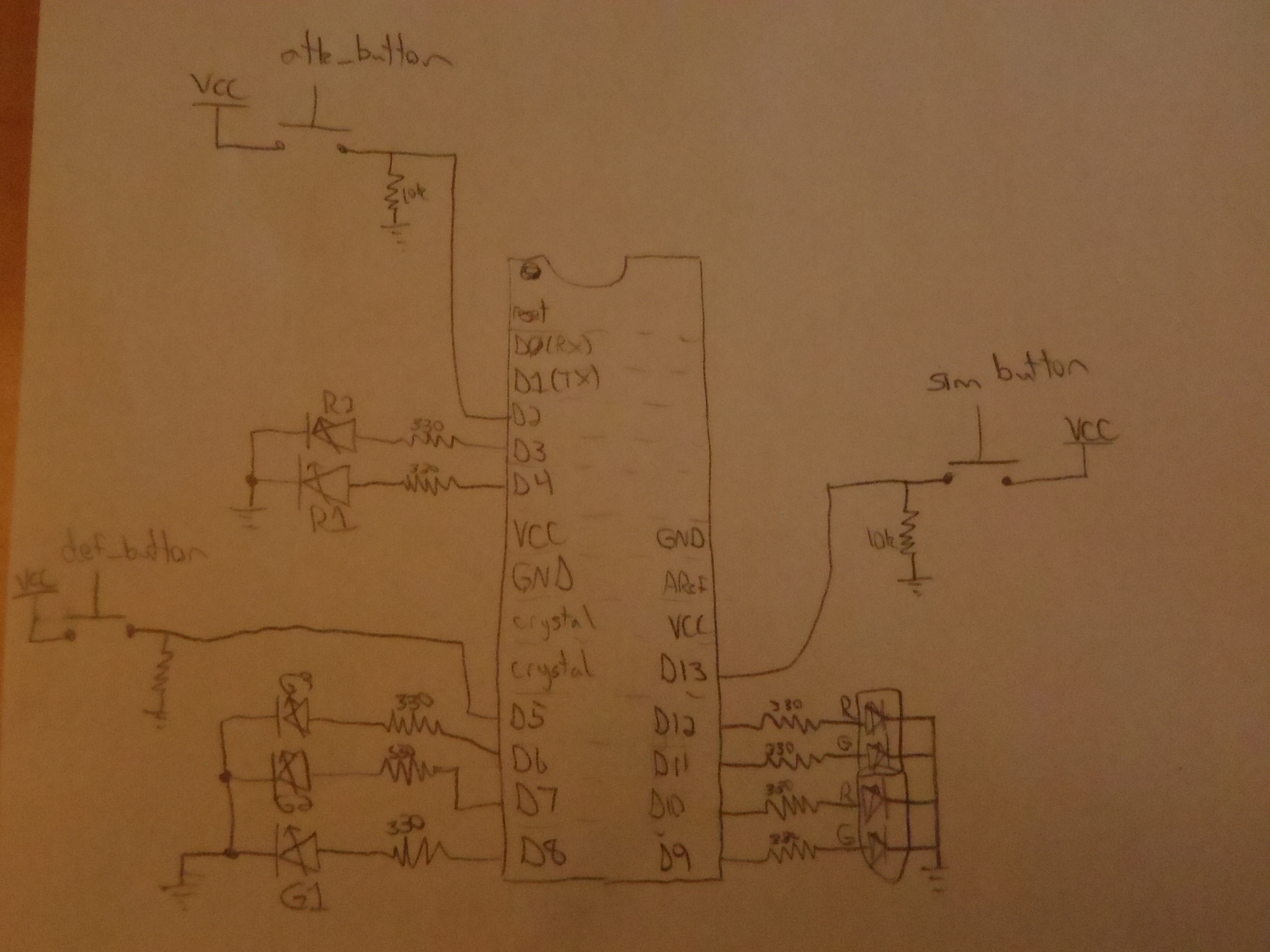
The circuitry is very straightforward so I hope you don't mind the terrible diagram.Circuit Top
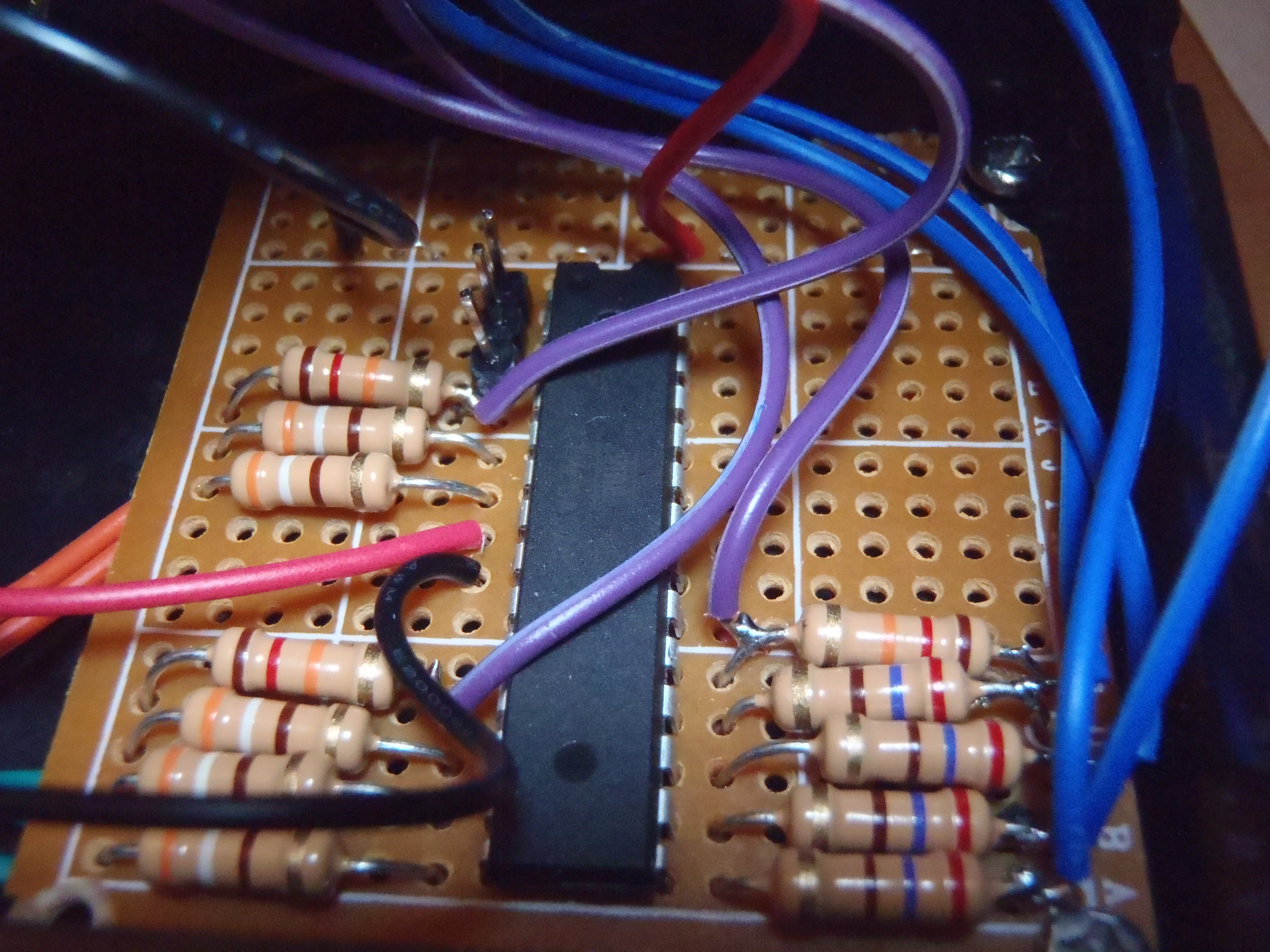
Since I'm lazy, and 10k and 330 ohm resistors always get used up, I chose resistors near to those values. I can get away with this because the value of these is not crucial. We'll pretend they are the right values! The 10k resistors are pull down resistors, and the 330 ohm just set the LED current. At the top left of the micro you can see the 3 header pins I added in for easy programming. Those pins are reset, tx, and rx.
Circuit Bottom
Lid Top
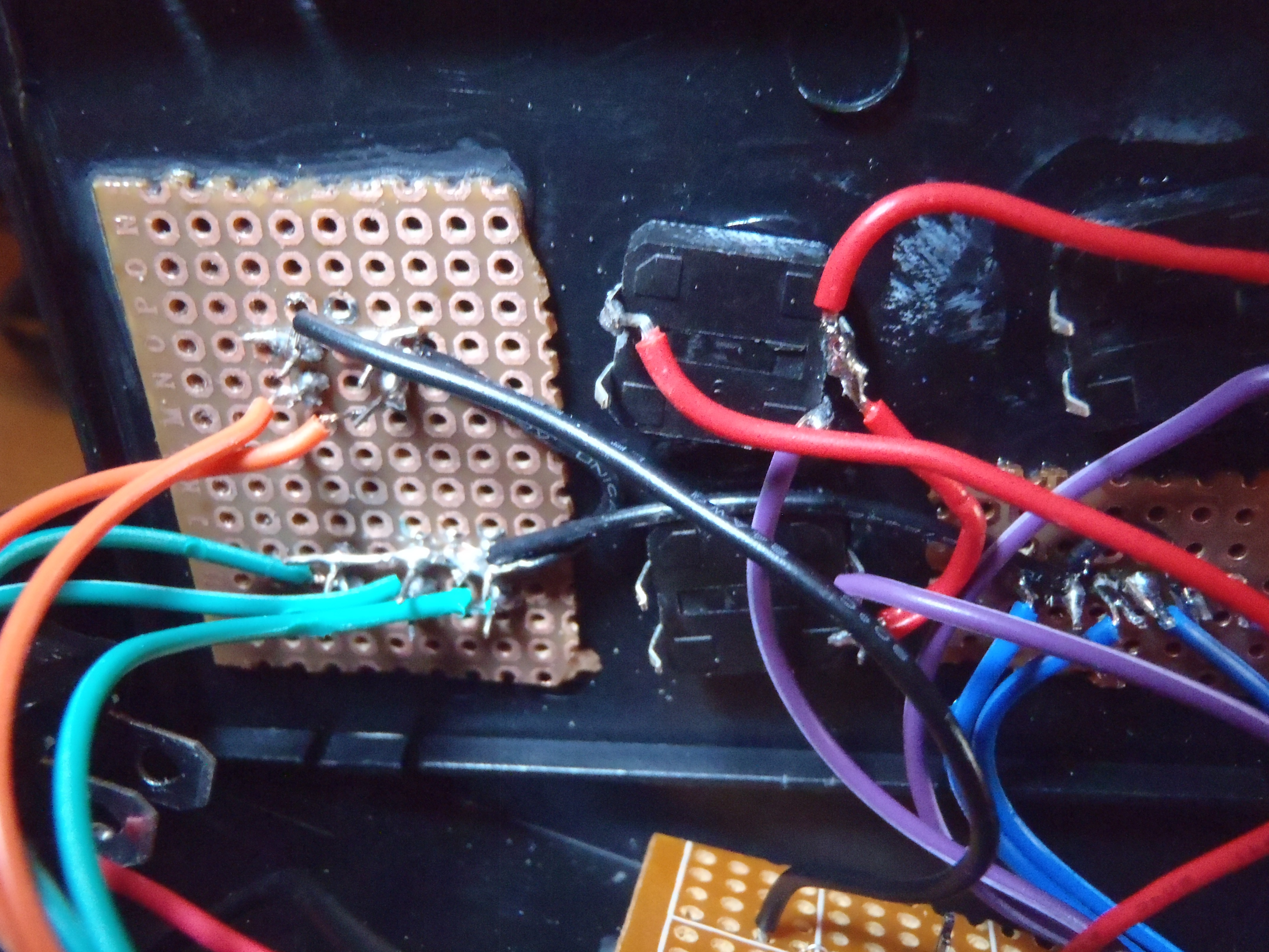
I used super glue and protoboard to get the LEDs and buttons in place. You can tell I really hacked this together. Not the best way to do it, but it works for a proof-of-concept device. Super glue and buttons definitely don't play nice. I ruined a few buttons with glue leaking in, but eventually got it right. The button contacts suffered a bit regardless, but since all I needed way to establish a low-to-high transition, it was good enough.
Here is the link to the case I used. Great price too.
-
On Random Numbers and Power Consumption
07/08/2016 at 03:27 • 0 commentsWhat is random?
I wondered to myself today, really just how good is the random() function from the arduino standard library? I looked it up, saw it was what I expected it to be called, and threw it right in. I made the mistake of not reading the whole page, however.
"If it is important for a sequence of values generated by random() to differ, on subsequent executions of a sketch, use randomSeed() to initialize the random number generator with a fairly random input, such as analogRead() on an unconnected pin."
Damn it.
Now that I pay attention, upon powering up, the results would be exactly the same each time if I only pressed the simulate button. I suppose this "random" function uses something like the program counter to generate the number, rather than a time-based counter. Since I would often play around with the army sizes at start up, I never noticed any pattern or flaw in the "randomization". Rookie mistake.
If I were wiser I would have prepared for a way to easily reprogram the device. I took a gamble that it would be perfect and I lost. Much like the random() function, the results were predetermined and I was destined to fail.
Power consumption considerations
Since this is a battery powered device, I wanted to make sure it wasn't hogging too much power to do such a simple thing. A good way to reduce power is to set up the microcontroller to use it's internal clock rather than an external crystal. Another is to reduce the clock speed. The following link is a nice solution to both of these problems with little work.
https://www.arduino.cc/en/Tutorial/ArduinoToBreadboard
This tutorial sets up the micro to use the internal oscillator at 8MHz. It is nice because it doesn't require looking at datasheets and spending times configuring things. That's why Arduino exists anyways right? Since low power consumption isn't a huge concern of mine, I'm fine with only dropping it to 8MHz. If power was a crucial consideration, I would drop the frequency way down to conserve power. The nice thing about this project is the simplicity and lack of ultra time-sensitive controlling.
Another perk to using the internal oscillator is of course not having to buy and solder in a crystal and capacitors! I'll definitely be doing it this way in all future projects.
Risk Battle Simulator
Love Risk, but hate constant dice rolling? With this device, there is no more inevitable dice falling off tables and knocking around armies.
 Scott Clandinin