Close
0%
0%

HDMI in to HDMI out on a ZYNQ based platform.

HDMI demonstration on the EMC2 development platform from Sundance with signal processing

Similar projects worth following
The demonstration runs on a stand-alone EMC² Development Platform PCIe/104 OneBank™ board feature a Zynq XC7Z030 with dual ARM9 CPU, a reconfigurable FPGA Logic and an interface to CPU specific I/O features.
The ARM processor core have direct access to the DDR3 memory that provides 1GByte of storage.
The purpose of this demo is to allow real-life data, in this case a video-stream from a HDMI Output to be loaded into the Zynq’s DDR memory and then displayed again on a second HDMI-Input device (typically a monitor).
In this demonstration, a VITA57.1 FMC® compatible Daughter Card is plugged to the EMC²-DP to provide HDMI input/output capabilities.
This demo shows how to implement computing intensive tasks in hardware by using High Level Synthesis tools.

Hardware design

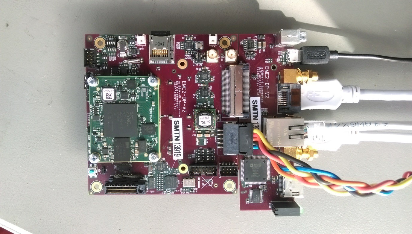
The demo is based on a customed design platform developed in Vivado 2017.2. The demo runs on a Zynq XC7Z030.

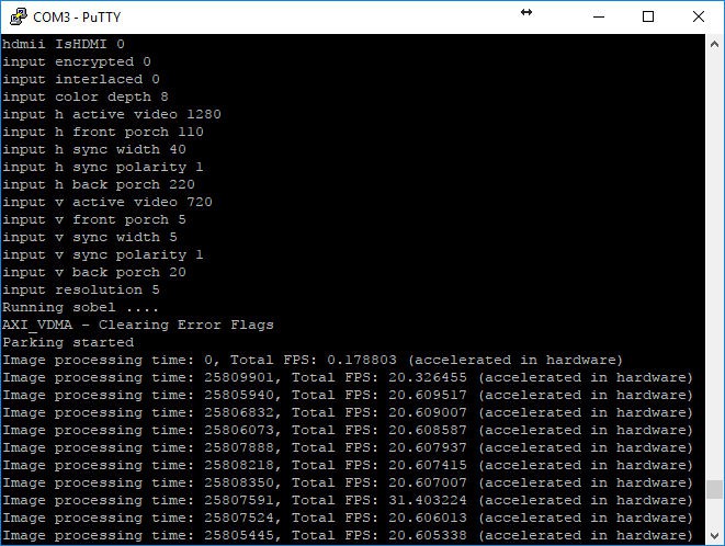
The resolution of the input and output video data is set at 1280x720 with a 65MHz frequency rate. 

For the video input and video output we used respectively HDMI input IP and HDMI output IP that already existed. The HDMI input component (ADV7611) and the HDMI output component (ADV7511) are configured by software at start up.

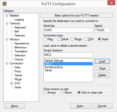
A UART interface is used to communicate and configure different part of the system (HDMI, VDMA, VTC).

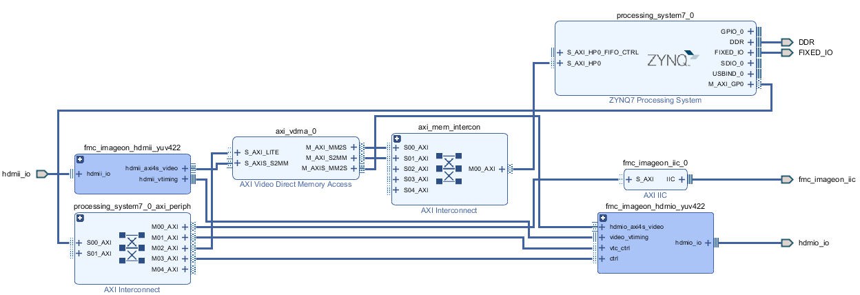
The Xilinx® LogiCORE™ IP AXI VDMA core provides the high-bandwidth direct memory access between the DDR3 memory and the HDMI peripherals.

This is a simplified view of the hardware design using Vivado 2017.2

Software design

Our demo is a bare-metal application executed on the ARM Cortex A9 processor. The project was developed with SDSoC2017.2 from Xilinx.

In our software the edge detection code is accelerated in hardware to improve performances.

The edge detection algorithm is producing a black and white video stream. Edges in each frame are marked as white and the remaining part of the figure is set as black.

The edges are detected by a Sobel filter. Each pixel is filtered by a 3x3 2D FIR filter. A nonlinear decision on the output of the filter provides information as to if the pixel is part of an edge or not. All computation is performed in fixed point. The Sobel filter is applied on the left half of each video frame for display purposes.

When the filter is accelerated, the main purpose of the software code is to control the advancement of VDMA frame pointers. Indeed, a triple buffer is used in order to display the newly computed frame a soon as the Sobel filtering is finished while, at the same time, processing the following input frame.

The output display is vertically split in half. The right side displays the video before being processed while the left side displays the video processed with a Sobel filter.

The software has been developed to highlight the benefit of hardware acceleration. In that respect, the output video display switches between the data processing done in software then done in hardware. The changes occur about every 15 seconds and highlights the greater performances achieved once the software is accelerated. In our case, the FPS is nearly 100 times faster:

·         0.35 fps (software)

·         31 fps (hardware accelerated)

Product Specification.pdf

Details about the demo and how to build it and run it.

Adobe Portable Document Format - 3.76 MB - 07/05/2016 at 11:50

Preview
Download

  • 1 × EMC2 Development Platform from Sundance
  • 1 × VITA 57.1 FMC-IMAGEON from Avnet
  • 1 × Trenz Electronic TE0715 (Z-7015)
  • 1 × STC-HD93DV HD DVI Output CCD, 720p, Color, Cased by SenTech
  • 1 × SDSoC2017.2

  • 1
    Step 1

    Running the demo

    1 Hardware

    1.1 Hardware requirement

    For the demo you will need

    • an EMC² board with a SEIC and a FMC Imageon board,
    • a HDMI screen
    • a computer running Windows 8 and above
    • cables: power,  mini USB to USB, 2x HDMI.
    • a HDMI source such as a camera

    1.2 Hardware setup


    Figure 1: Hardware setup

    1. Connect the power cable to the EMC² board but don’t switch the power on for now.
    2. Connect the USB cable between the EMC² board and the computer.
    3. Connect the computer screen (or  HDMI camera) to the HDMI in on the FMC board and the other monitor to the HDMI out on the FMC board.

    2 Software

    1. Copy to the micro SD card (previously formatted as explained here: http://www.wiki.xilinx.com/Prepare+Boot+Medium) the file: BOOT.bin from the “2017.2\workspace\emc2_hdmii_hdmio_sa\Release\sd_card” folder.
    2. Insert the micro SD card and switch the power on to boot the EMC² board.
    3. Open a serial console (for example Putty) with the following settings:Speed: 115200Data bits: 8Stop bits: 1
      Parity: NoneFlow control: None

    Figure 2: Serial console settings

    In the serial console, you should see information about the status of the configuration of the different components from the design (HDMI, VTC, VDMA). Once all the components in the system are configure the video output will be displayed on the monitor.

  • 2
    Download the source files

    The source files can be downloaded from here:

    Hdmi in to Hdmi out demo

View all instructions

Enjoy this project?

Share

Discussions

Similar Projects

Does this project spark your interest?

Become a member to follow this project and never miss any updates