Close
0%
0%

Visible Light Communication for the masses

This project will focus on making current research in field of Visible Light Communication (VLC and LiFi) usable and meaningful for use...

Similar projects worth following
So far I spend some serious amount of time developing usable low-cost VLC solution that can find its way to every day use in PAN networks. My primary idea is to enable Sensor/IoT to MCU/SOC or MCU to SOC low power intercommunication (M2M) in visible light spectrum.
VLC systems are far beyond EM spectrum that is regulated by gov. agencies and is by default free, open and dose not require licensing. But best part is its width that can in future provide million times greater bandwidth that whole 10k-300GHz Radio EM spectrum.
Lot of researcher and high-profile academic, and companies labs are making ground breaking discoveries in this field (so far like 100Gbps etc.) but all of them in state-of-the art labs are using extremely expensive and not so common equipment that rest of the mortals can only dream of but...
If we want to make VLC (like LiFi) usable for small IoT systems it can not be more expensive then MCU/SoC systems and can not draw more than 1W to max 5W of power.

For start I will direct you to read some of my published research papers:

Analysis of Visible Light Communication System for Implementation in Sensor Networks

Some other papers are on Serbo-Croation so if it is not your native you will need some translator :( ...so I will attach PDF file)

All my further research and solutions will find its place in this project. I suggest you check those papers to get inform about transmitter and receivers circuit that use low-cost but still hi-performance components.

To fully benefit from observed 80-100MHz clock transmission per color channel we will focus our efforts in future on developing better receivers with flat bandwidth greater than 200MHz, and on hi-performance asymmetric-pulse generators in nano seconds range. Preserving whole system within power consumption 1-2W range without use of unhealthy and hazardous technologies like LASER LEDs.

154-Analysis of Visible Light Communication System for Implementation in Sensor Networks.pdf

Visible Light Communication technology today provides an opportunity for high speed and low cost wireless communication. In this paper, we give solution based on our research, relating to the VLC application in sensor networks in IoT systems.

Adobe Portable Document Format - 753.52 kB - 07/07/2016 at 02:43

Preview

Model multikanalne VLC opto-telekomunikacije razvojnih SoC i IoT senzorkih sistema-RC2.pdf

Model of multi-channel VLC opto-telecommunications between the SoC development and IoT/sensor system This work is a continuation of research in the field of analysis, modeling and establishing an optimal model PAN VLC opto – telecommunications between SoC development computer, micro-controllers, IoT and sensor systems. The work presents the concept and design solutions of receive – transmitting electronic circuits intended to establish peer – to – peer communication over short distances between devices with high energy efficiency. A large number of such devices in a relatively small area is somewhat of a challenge when we consider the expectations for these devices operating in the available classic transceiver ISM RF fields, currently available, on the other hand the width of the available range of the light part of spectrum represent a huge potential.

Adobe Portable Document Format - 902.79 kB - 07/07/2016 at 02:40

Preview

  • 5 × OSRAM SFH 213 (PIN) photodiode Opto and Fiber Optic Semiconductors Photodiodes 400 nm to 1100 nm Tr/Tf=5ns
  • 5 × VIshey BNP 10 (PIN) photodiode Opto and Fiber Optic Semiconductors Photodiodes 380 nm to 1100 nm Tr/Tf=2.5ns
  • 2 × Red LED 5mm, CREE, If = 20mA, 23500mcd,
  • 2 × Green LED 5mm, MARL Nichia, If = 20mA, 37700mcd,
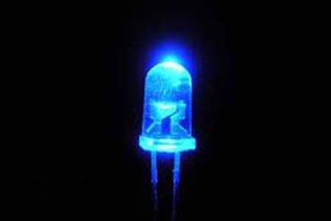
  • 2 × Blue LED 5mm, Knightbright, If = 35mA, 18000mcd (OR Blue LED 5mm, AVAGO, If = 20mA, 12000mcd)

View all 17 components

  • Single LED source - multiple channel separation

    Jovan12/31/2016 at 18:37 2 comments

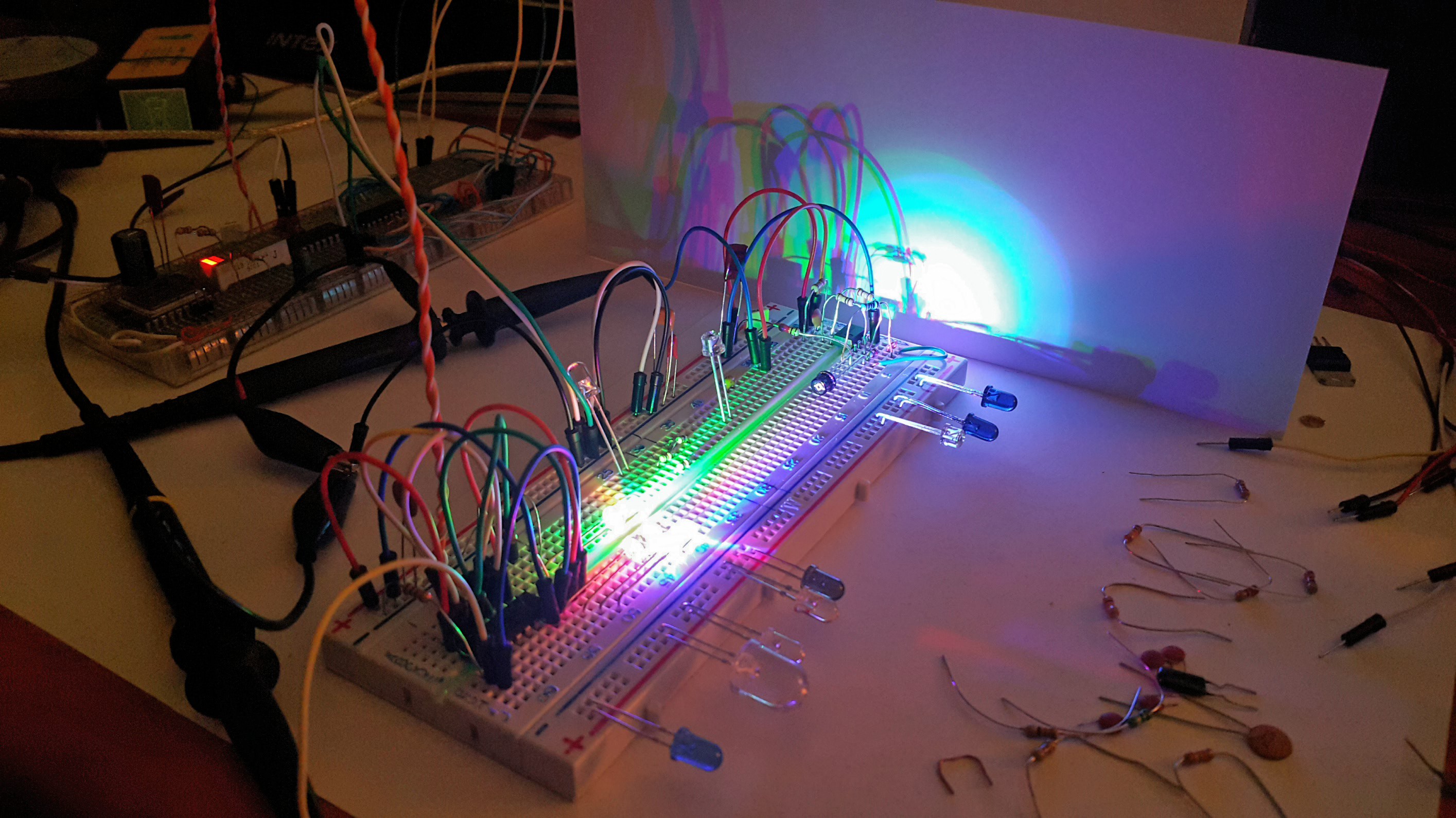
    For the end of this year I would like to share with you a simple solution for multi channel separation of single LED source.

    (it operates on 14MHz pulse per channel with 30% Duty and phase shift of 120deg per channel)

    Happy New Year.

  • It can be used even when daylight fills the room

    Jovan09/08/2016 at 22:17 0 comments

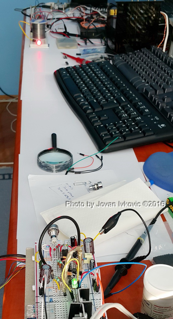
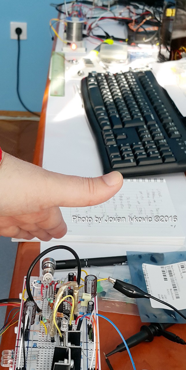
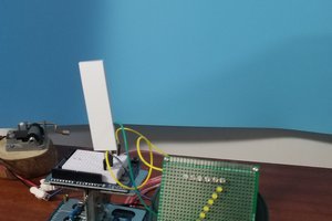
    Until new research results and developed solution came in a few weeks I'd like to share some images of how it work even in daylight with one red LED emission diode at 1.1m distance from receiver.

    First it should be noted that the level of ambient light in the darker parts of the room was about 10EV (~2600 Lux) and that red LED is at ~18000 mcd at peek. Pictures was taken while testing 5..10MHz square pulse with 10..50% duty cycle and it (RC) degradation on receiver side with distance.

    Green LED on the receiver lights up when signal is detected with the level greater than 3V. As the latest version of the receiver with 3 Op.Amps also serves as a band-pass filter, ambient light as constant at the level of ~ 11EV is suppressed. In the second picture is shown that hiding of red LED signals as emission source do not excites the receiver's green LED although ambient light level is high enough to do that.


  • Word or two about polarizatio of light

    Jovan07/09/2016 at 21:11 0 comments

    As we all already know light (as any other EM) can be easly polarized. By seting different polarization angles of emited ray it is posible to have much more then one light beam of same frequency (color) in the same propagation path.

    In next video you can se how it is posible to do more then just masking of light source with 3 polarized filters. I also demonstrate some posible logical operations with light so watch carefuly ;)

  • Color ch. filtering

    Jovan07/07/2016 at 17:08 0 comments

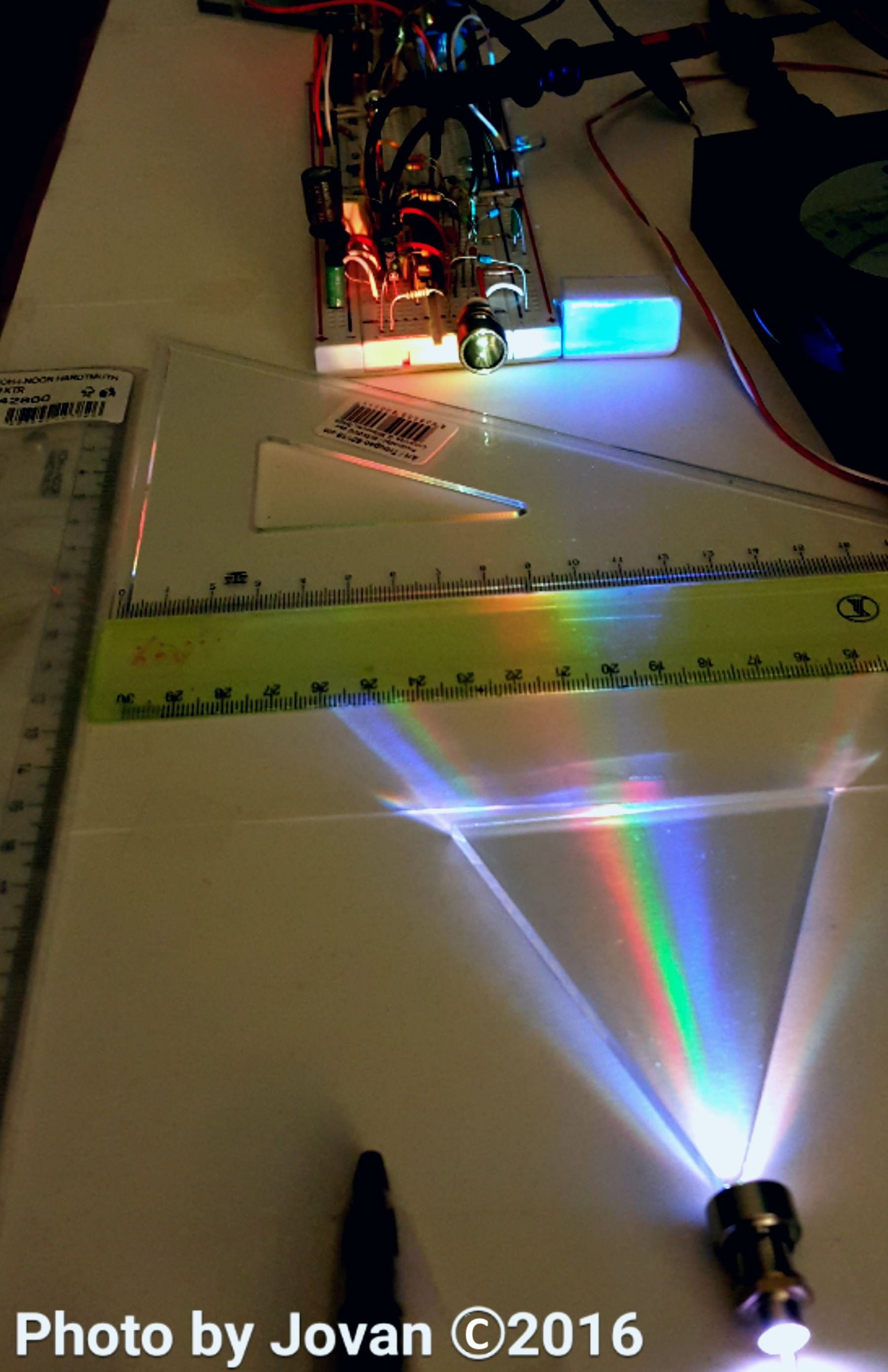
    We all know that Light Emitting Diode (LED), convert electrical energy into light on the basis of recombination of electrons and holes that release energy quants in the form of photons which have frequency dependent on the material from which the semiconductor layer is made. As a semiconductors it can be turned on and off at high speeds, which can be used for directly sequenced coding, part of an orthogonal coding is also possible because on LED’s we can control to some extent the level of photon emission, that is light intensity.

    In addition, LEDs are available in several different color shades, which allows the application of color separation filters corresponding to the reception so Space Time Coding (STC) be carried applied, i.e. each color can become a separate channel.

    Light due to its dualistic nature in addition to its quantum also inherent all EM waves characteristics, and can be polarized. The standard IEEE 802.15.7-2011 foresaw the possibility of the existence of 3 different Physical Layer (PHY) operational mode in which will provide bit rate up to 96Mbit/s for optical clock rate of 24MHz and 16-Color Shift Keying (16-CSK) modulation (PHY III Optical Mode)

    Knowing all of that we can try and make color and polarization filtering of separated color chanels.

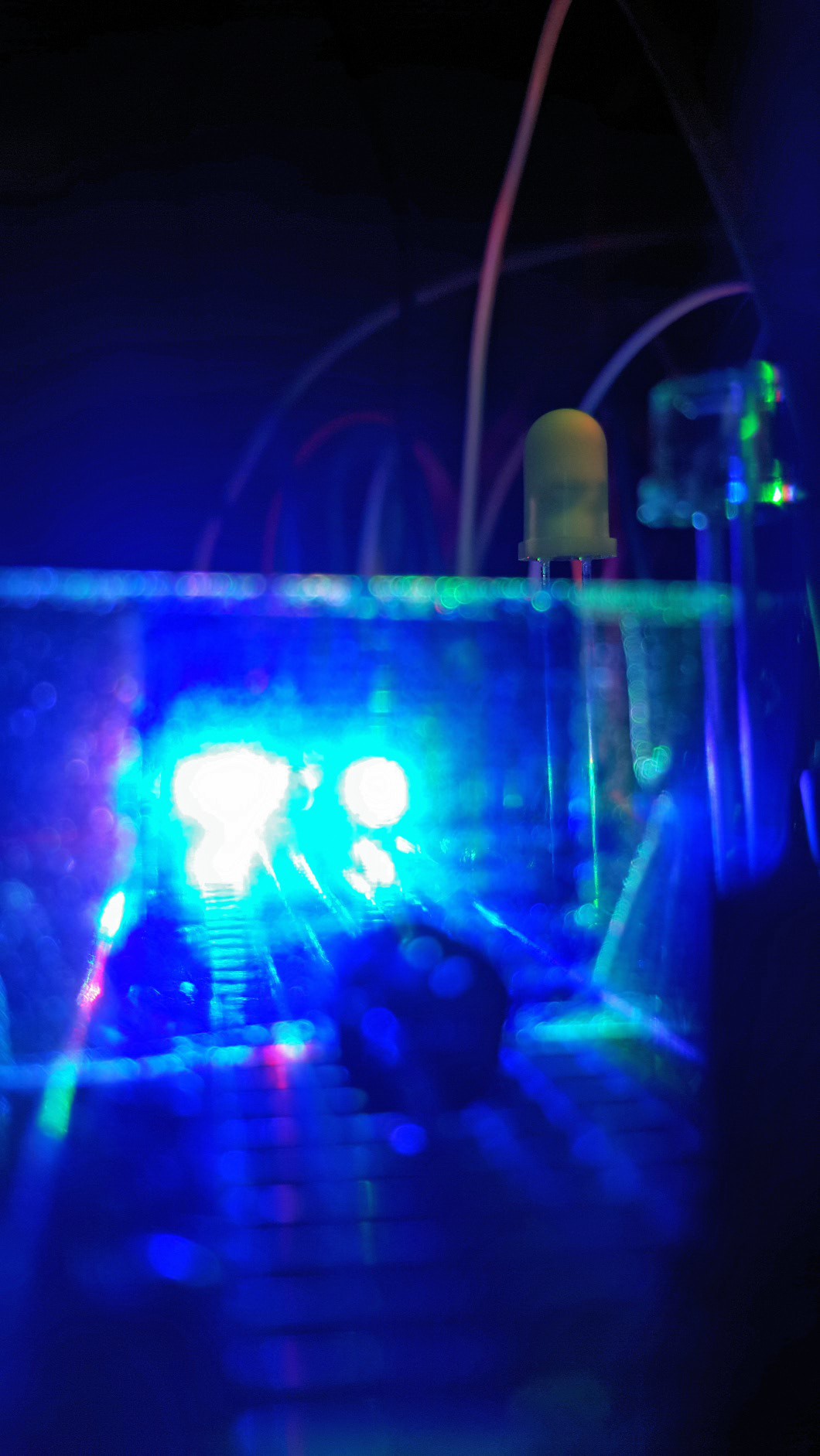
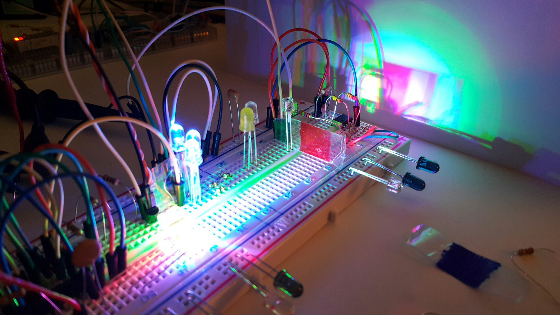
    Blue filter pass blue and portion of green LED light.

    Red is doing oposite.

    Setup with color stickers :)


  • Ultra bright <75mA LED

    Jovan07/07/2016 at 16:50 0 comments

    Resonant Cavity Light-Emitting (RCLED) diode, (whose price exceeds several thousand dollars) or diffusely scattered laser LED diodes would be ideal solution if we can ignore price, cost of assemby and health hazards.

    With the aim to focused on the development of sustainable solutions using the widely available technology (preferably more accessible prices) that can be of applied in IoT and sensor systems and whose total power consumption does not exceed 2W (maximum 5W). Taking into account the above guidelines after the initial consideration and experiments we decide not to use ≥1W Hi-Power LED, since their nominal supply current while running is ≈350mA, and pulse at the beginning of the emission cycle goes through 500-550mA. As a substitute in the solution was applied Ultra-Bright / Superbright (UB) 5mm LEDs designed to work in outdoor daylight condition in signaling devices and large LED panels. UB-LEDs are on the market in average 3 to 5 times cheaper than 1W Hi-Power LED, provide a focused beam of the semi-angle φ1/2 of 8-30° with the intensity of light emission from 8000 to 37000mcd (mili candela) at Forward current If = 20-35mA (with 75-90mW we can find even > 57cd UB-LEDs ).

  • LED light

    Jovan07/07/2016 at 16:32 0 comments

    First thing you will notice is that 1W or stronger LED light bulbs are out of projects scope.

    Main reason is power consumption that exeeds limits of 5W. If we plan to make emiters with 3,4 different color ch. and IR then LEDs with nominal power => 1W is out of scoope.

  • 1st step know problem and solutions

    Jovan07/07/2016 at 03:55 0 comments

    For start I suggest we all read those papers that was linked in details. Then we can move on to next step in research.

View all 7 project logs

  • 1
    Step 1

    In fist and second paper you will find electronic design of key elements like transceiver and receiver part.


  • 2
    Step 2

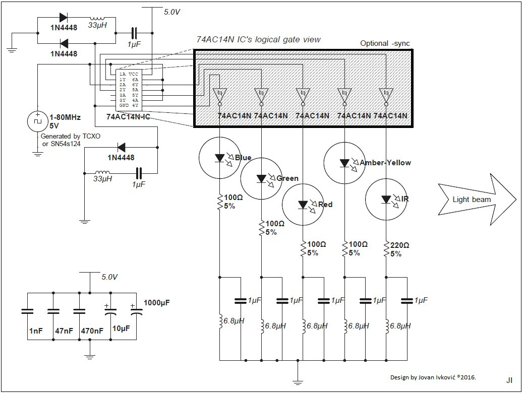
    To find optimal speed of LED pulse transmission that depend on your setup and used component I suggest you first build simple but fast and effective LED driver.

    I suggest this design, and as you already read from presented papers I tested under real work conditions more then 10 different TTL/CMOS circuits until I find optimal solution that preserve speed and signal integrity while providing enough power to several LED's.

    As you read from 2nd paper this design can be improved by reducing number of LED's per one IC and lowering resistor values in according to theirs Vf. Any way playing with this design will help you start and understand.

    Parallel coupling of ports as people on Ronja project dose, can help you increase If current but at expense of drawing more then 1W for the whole setup that we try to preserve. On the other hand use of ultra-fast MOSFET Drivers like Microchip's TC4427 (max drive up to 1.5A) shows as excellent solution only for low speed < 5-8MHz solution for full power IR emitter. Observed delays of 25-40...60ns choke signal geometry above 10MHz. Keep in mind that 100-200...500mA pulse with few volts of Vf can produce serious ringing and signal degradation in circuit while it exceed 1W limit.

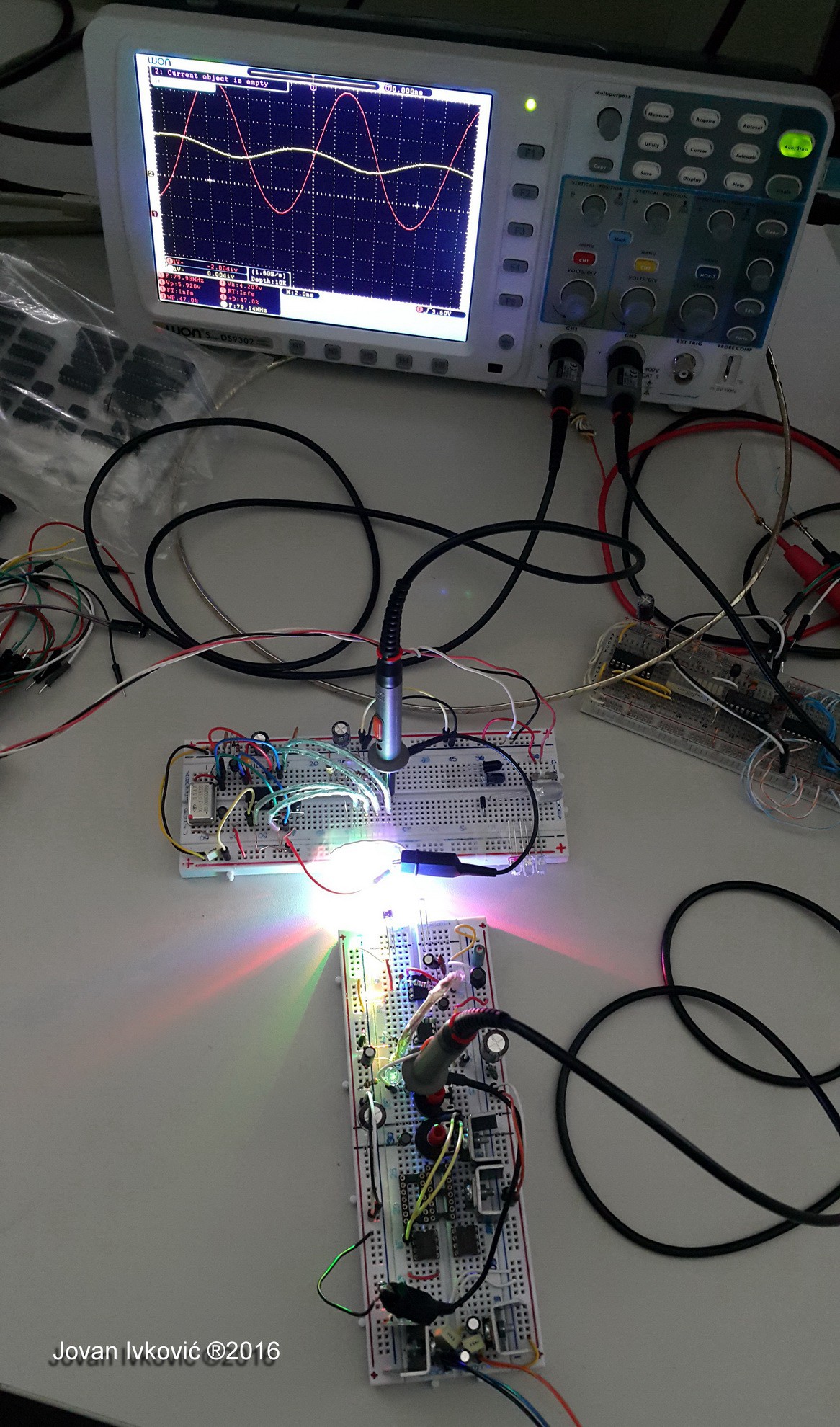
    Any way this solution can drive you up to 80MHz.

View all instructions

Enjoy this project?

Share

Discussions

Jovan wrote 12/31/2016 at 18:13 point

Happy New Year, Best  Wishes and let light shine on us in 2017. 😉

  Are you sure? yes | no

Le Dung wrote 12/04/2016 at 11:36 point

Currently, I'm thinking to use VLC for IoT applications. Could you tell me how much the maximum distance between transmitter and receiver in your project is? 

  Are you sure? yes | no

Jovan wrote 12/04/2016 at 18:03 point

Hi Le, at the beginning of my work I had to put some limits in various areas as you already read, so to preserve level of power consumption of transmission and system as a whole it was necessary to sacrifice something, and that was the range of the system.  The expected maximum working distance is in the range of PAN networks 5 to max 10m.  

Do not forget  inverse-square law  stating that a specified physical quantity or intensity is inversely proportional to the square of the distance from the source of that physical quantity.  

So when you put all of limitations as < 1~2W power, size/bulkiness of whole device that can not have 120-150mm lenses etc. and should have and maintain ultra wide bandwidth you end up with something that work well in 3..5m.

  Are you sure? yes | no

Jovan wrote 09/09/2016 at 20:54 point

Right, what you can see in those 2 papers was early work with just direct sequence ie. pulse modulation. Unfortunate I can not share with you to much right now, because papers that I am working on require exclusivity :( ...until that materials get published can not disclose to much. But you can take my word for it that LED light signal can be easily modulated with more complex modulation scheme.

Interesting question, if we can directly control some LCD element with its polarization at 80MHz we would de facto have photonic-transistor. For now I think of polarization in a
more static way, as a mean for further channel separation.

You can send 50MHz but due to LED's power-bandwidth product limitation it will be just a fraction of full LED's power on example 1-2MHz, so you will need high amplification and band/high-pass filtering to separate signal from very close background noise.

You can find tested circuits schematics in my 2nd work: https://cdn.hackaday.io/files/12556537195904/Model
multikanalne VLC opto-telekomunikacije razvojnih SoC i IoT senzorkih
sistema-RC2.pdf.
... all I can say is that right now I am making that
new design from "Slika 7".  Design from "Slika 8" is long time operational and well tested and you can see it in my last  (yesterdays) Log. It has modification in fist stage Op.AMP feedback resistors value descried to 5-10k. 

What I also have is some new improved designs to that on "Slika 7" design pushed up to ~100MHz... but reality is always more complex and with issues in comparative to simulations and that dose not work as intended to... for now.

  Are you sure? yes | no

Lars R. wrote 09/09/2016 at 08:08 point

Do you have a simple/basic circuits (schematic and 2 or 4-layer pcb) that require as few parts as possible for sending and receiving with 50+x MHz and with receiver sensitivity of at least 12 bit?

I fail to see frequency modulation and phase modulation. You can use multiple colors or polarization filters as you can use multiple AM radio transmitters (each with its on frequency and antenna orientation). Or can you change polarization @80MHz and have a receiver that follows changes in polarization @80MHz?

  Are you sure? yes | no

Jovan wrote 09/09/2016 at 20:48 point

Right, what you can see in those 2 papers was early work with just direct sequence ie. pulse modulation. Unfortunate I can not share with you to much right now, because papers that I am working on require exclusivity :( ...until that materials get published can not disclose to much. But you can take my word for it that LED light signal can be easily modulated with more complex modulation scheme.

Interesting question, if we can directly control some LCD element with its polarization at 80MHz we would de facto have photonic-transistor. For now I think of polarization in a more static way, as a mean for further channel separation.

You can send 50MHz but due to LED's power-bandwidth product limitation it will be just a fraction of full LED's power on example 1-2MHz, so you will need high amplification and band/high-pass filtering to separate signal from very close background noise.

You can find tested circuits schematics in my 2nd work: https://cdn.hackaday.io/files/12556537195904/Model multikanalne VLC opto-telekomunikacije razvojnih SoC i IoT senzorkih sistema-RC2.pdf... all I can say is that right now I am making that new design from "Slika 7" and design from "Slika 8" you can see in my last  (yesterdays) Log. 

I also have some new improved designs to that on "Slika 7" for ~100MHz ...but reality is always more complex and with issues in comparative to simulations and that dose not work as intended to... for now.

  Are you sure? yes | no

Jovan wrote 07/13/2016 at 03:58 point

If we use 16-Color Shift Keying (16-CSK) modulation suggested by IEEE 802.15.7-2011 for  Physical Layer and bandwidth of just 100MHz with suggested 4-5 separated color channels, without exaggeration, we can say that 2Gbit/s data transfer rate over LED based VLC is real.

  Are you sure? yes | no

Jovan wrote 07/13/2016 at 03:46 point

Before we start making photo sensor with flat and very wide bandwidth (wide enough to pass up to 100MHz) needed to sense ultra fast LED flashing rates, let us think for a moment how fast in Mbps this optical link can be. With bandwidth of 80MHz by Shannon–Hartley theorem we can get like of 350Mbit/s for SNR ~20dB per one color channel. Of course, to get that we need adequate modulation and coding to get that but about that we will talk later. Now lets focus o rensponsive, sensitive and wide photo sensor.

  Are you sure? yes | no

Similar Projects

Does this project spark your interest?

Become a member to follow this project and never miss any updates