 Jovan
JovanFor start I will direct you to read some of my published research papers:
Analysis of Visible Light Communication System for Implementation in Sensor Networks
Some other papers are on Serbo-Croation so if it is not your native you will need some translator :( ...so I will attach PDF file)
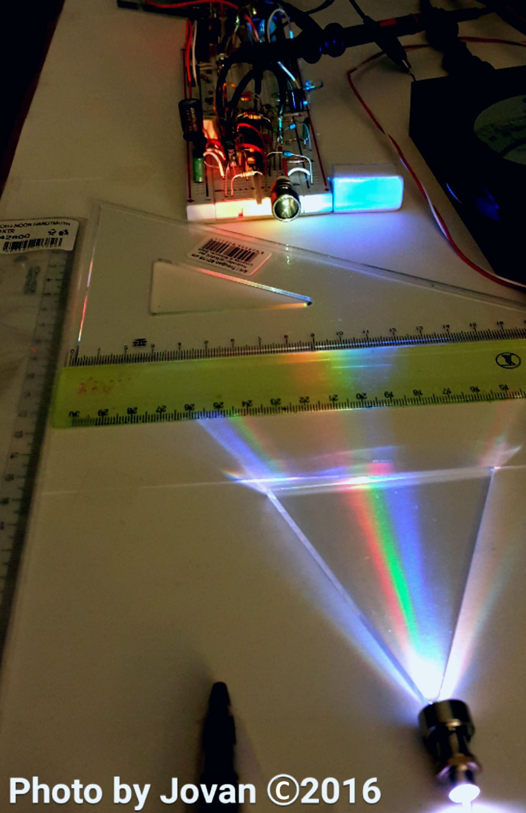
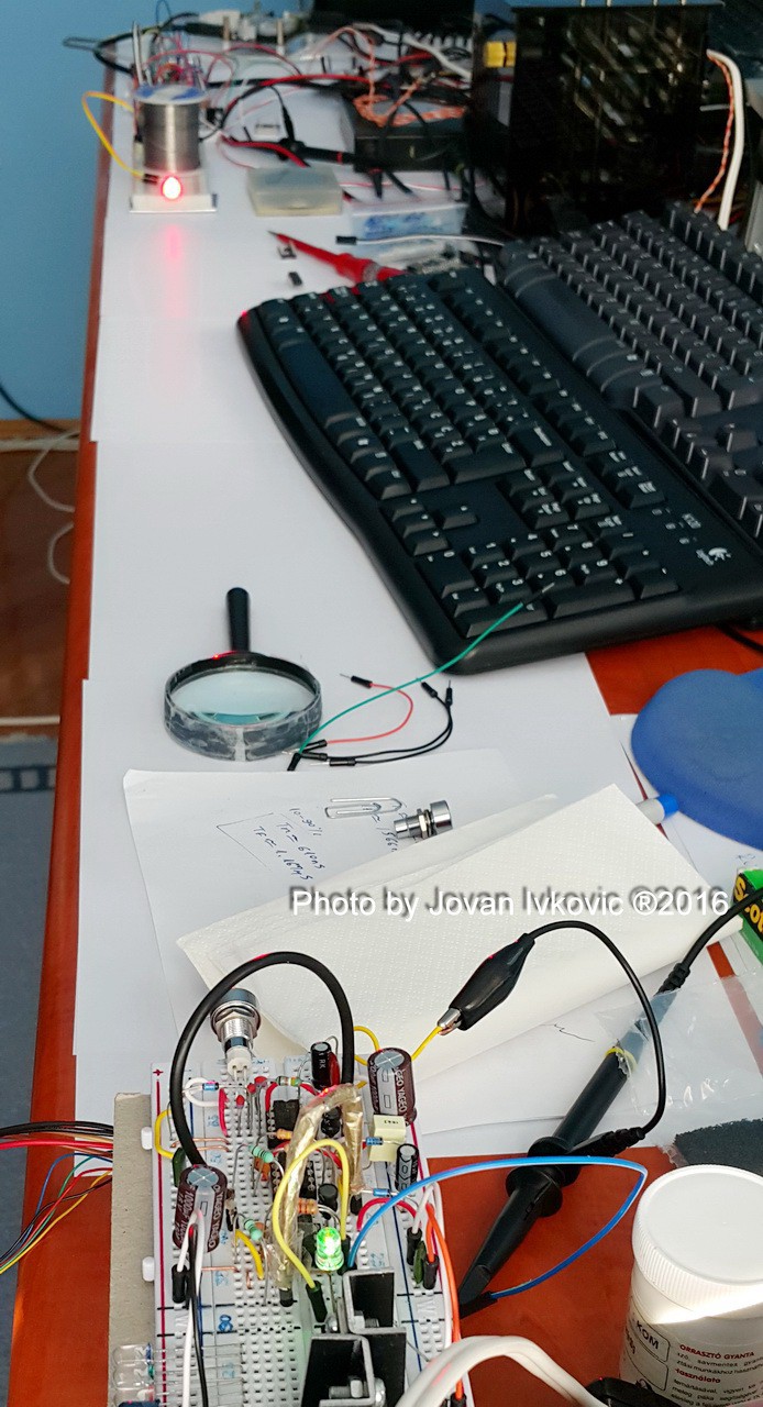
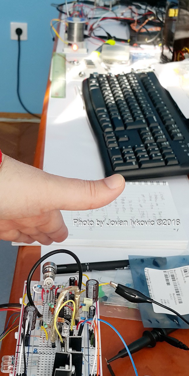
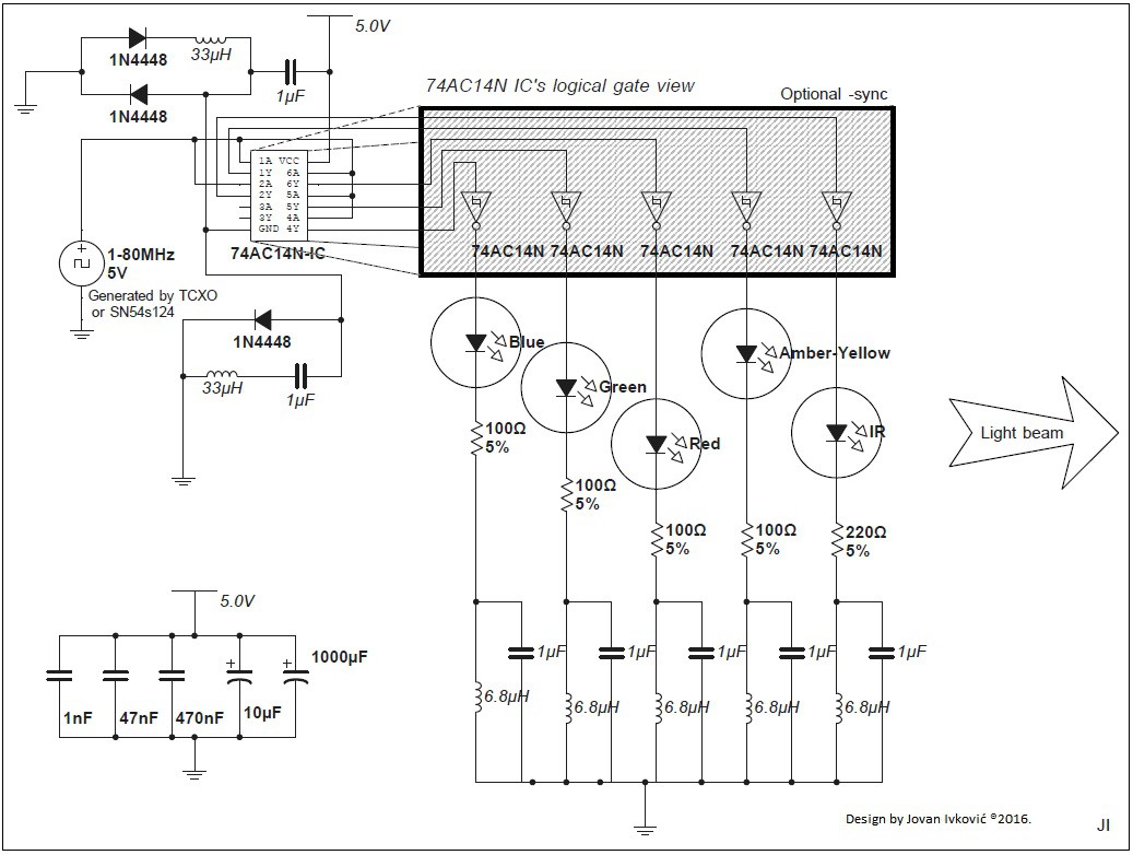
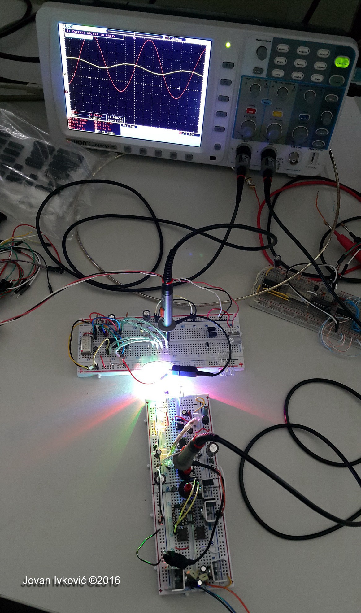
All my further research and solutions will find its place in this project. I suggest you check those papers to get inform about transmitter and receivers circuit that use low-cost but still hi-performance components.
To fully benefit from observed 80-100MHz clock transmission per color channel we will focus our efforts in future on developing better receivers with flat bandwidth greater than 200MHz, and on hi-performance asymmetric-pulse generators in nano seconds range. Preserving whole system within power consumption 1-2W range without use of unhealthy and hazardous technologies like LASER LEDs.
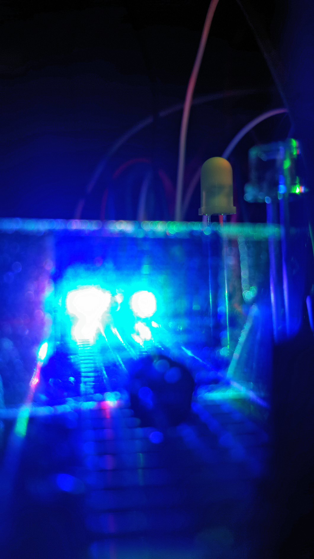
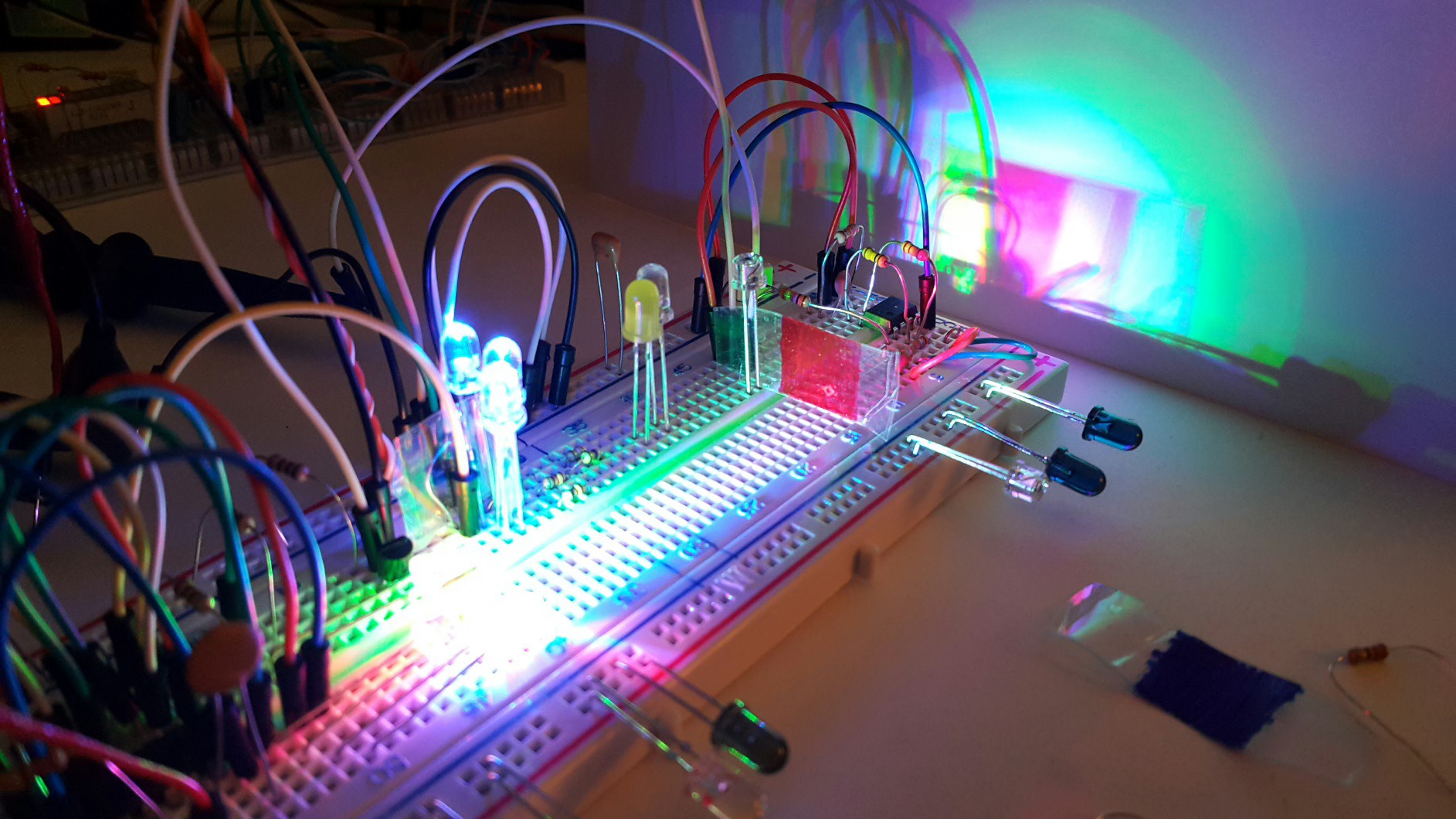
 Setup with color stickers :)
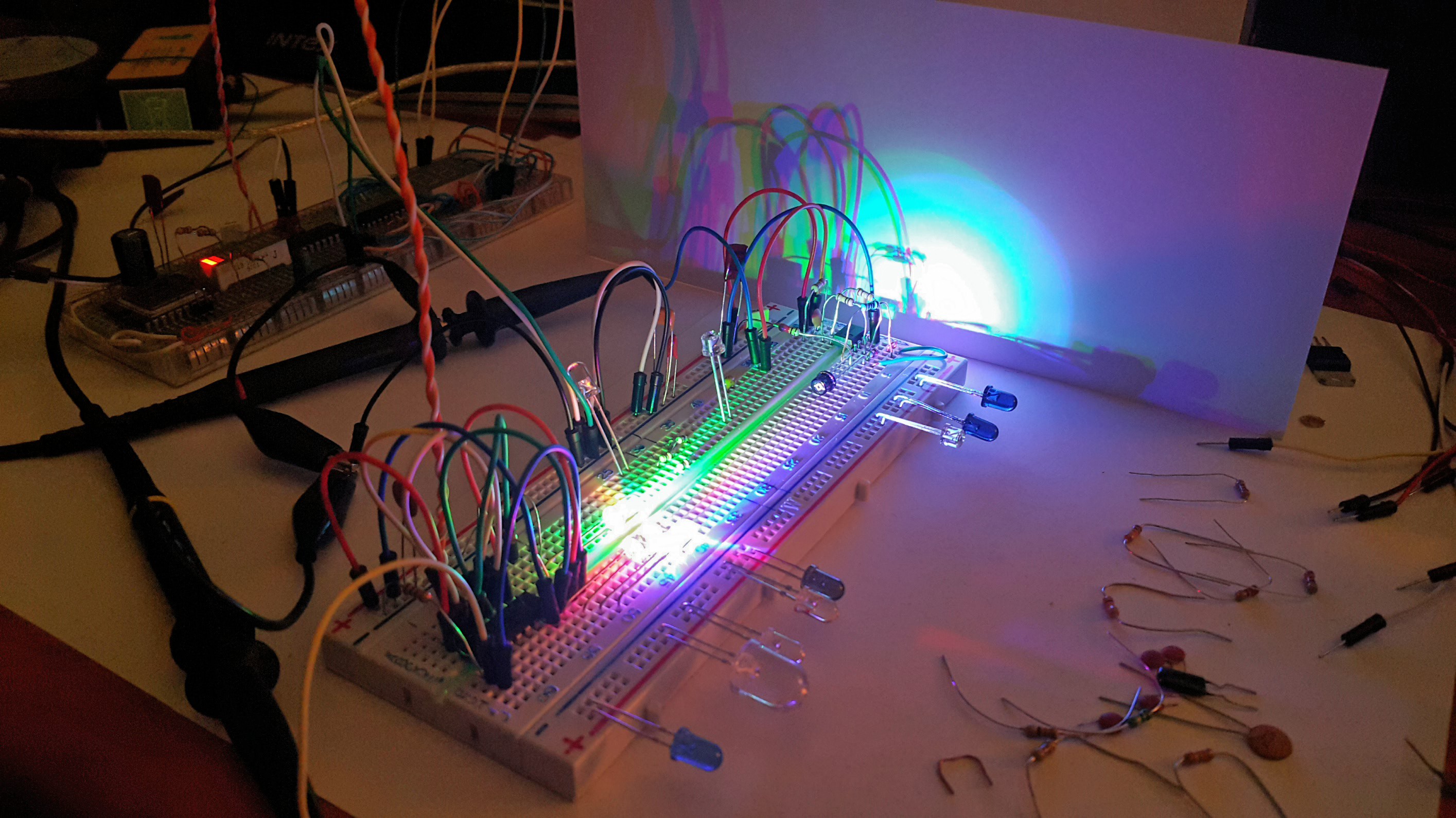


 richardginus
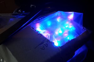
 James Cannan
 Ana
Ana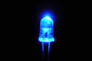
 Ben Hartmann
Happy New Year, Best Wishes and let light shine on us in 2017. 😉