 John Whitmore
Introduction
This all started with the re-wiring of a 1982 Mexican Volkswagen Beetle, many years ago. The result of that project was a mess. The car functioned, but in terms of an elegant solution to the wiring problem it certainly wasn't that. Fast forward and another project vehicle and another re-wiring problem. The problem space has changed very little over the years, but my proposed solution to the problem has to be an improvement on past attempts. That's when I discovered CAN Bus and what appears to be the obvious solution to the problem, (time will tell).
The Hardware
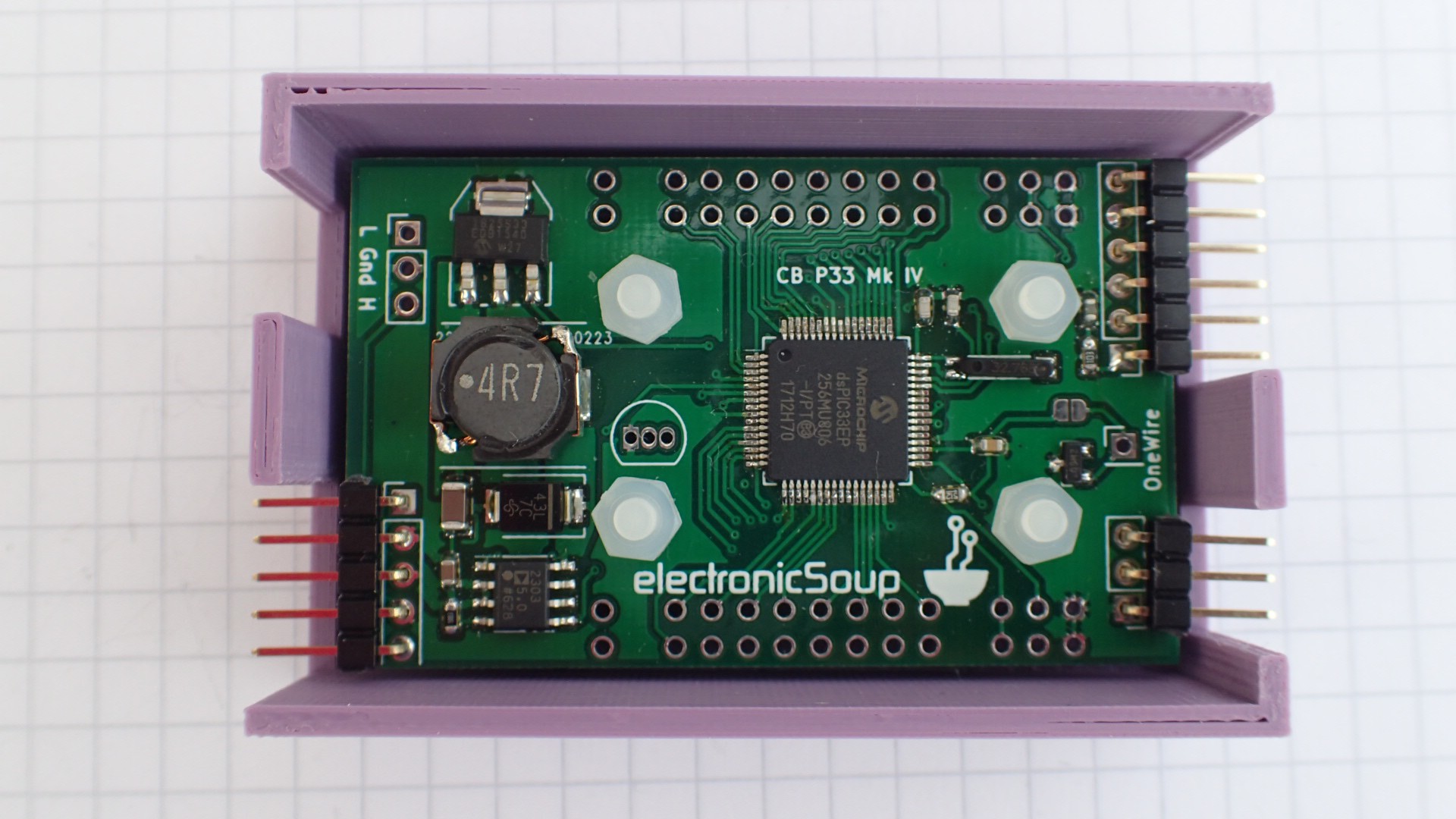
Given my discovery of CAN Bus protocols what I now needed was a simple micro-controller based board, like the Arduino, which talked CAN Bus and to which I could attach the necessary expansion boards to drive the various 12V electronics of the project vehicle. My search at the time didn't result in a satisfactory answer to my requirements. There were CAN Bus expansion shields for the Arduino family of boards, but once married to the Arduino the shield tied up the expansion slot and further 12V automotive electronics would be difficult to add. I could have created my own Arduino expansion shields, which each had a CAN Bus interface as well as 12V electronics, but that didn't appear to be the best solution. The obvious answer, to me, was to create my own micro-controller board which included all the CAN Bus, and higher level management protocols to which various expansion boards could then be added. The result is the cinnamonBun:
Ultimately this device will be Open Hardware but I'm hoping to get it into a vehicle, to test it to some extent before doing so. I'm hoping to catch any obvious, and potentially embarrassing, school boy errors before opening myself up to ridicule ;-) once tested I'll be happier to Open the device as a beta version and who knows perhaps sell a few, to pay some bills.
The Software
The problem space does not simply require Hardware but the Software that simplifies the solutions to distributed control problems. Ultimately the aim is to have an underlying Software Architecture which allows a simple Application code architecture, much like the Arduino, where developers have to create just two functions, one to initialise the CAN Bus Node and the other to add processing to the CAN Node's main even loop. There are three levels to this SW Architecture:
libesoup
At the lowest level is an Open Source LGPL licensed library of code which offers a simplified interface to the Hardware features of both the Microchip dsPIC33EP256MU806 based cinnamonBun, and the features of the cinnamonBun itself. Currently the library includes Hardware timers, UARTs, SPI, OneWire etc. etc. but more functionality will have to be added as more problems are tackled. At the time of writing, for example, I have still to tackle Analog inputs. This library of code libesoup is already Open to public scrutiny on github.
ES_CAN_Node
On top of the low level libesoup library is the code which manages the CAN Node. This code manages the protocols and the housekeeping associated with managing a node on the CAN Bus network. I'm reluctant to use the term OS because, whilst the code does manage lower level functions, so that higher layers can ignore the details, it is intended to be as small as possible, as it's intended target is a micro-controller. There will be no thread scheduling or memory management, those features aren't, at present, required to solve the problem being solved.
The CAN Node management software is Open and licensed under the GPL and can be obtained from github. If libesoup is a work in progress then ES_CAN_Node is even more so. Features like system monitoring and over the CAN Bus updates have yet to be tackled. But it is a start and getting the Nodes into a vehicle will hopefully prove the concept and justify further work.
The Application
As mentioned above the Application layer is defined in two, Arduino like, functions:
result_t app_init(uint8_t io_node_address, status_handler_t handler)
{
}

result_t app_main(void)
{
}
Because the ES_CAN_Node software is managing the lower layers the Application layer can simply declare an interest in receiving CAN Frames of a particular Identifier, or range of identifiers given a suitable mask. The application simply registers a CAN Frame handler for a range of frames and the handler will be passed any received frames matching the registered criterion. The result if an event driven Application with minimum code to write and maintain.
void handler(can_frame *frame)
{
}

result_t app_init(uint8_t address, status_handler_t handler)
{
    result_t               rc;
    uint8_t                loop;
    can_l2_target_t        target;

    node_address = address;

    /*
     * Register a CAN Frame handler
     */
    target.filter  = CAN_IDENTIFIER;
    target.mask    = CAN_MASK;
    target.handler = handler;
    rc = frame_dispatch_reg_handler(&target);
    RC_CHECK
}
In the above example where an Application registers a CAN Frame handler the Application might not add any processing to the main loop of ES_CAN_Node and leave the app_main() function empty, thus becoming a totally event driven application.
At present both the ES_CAN_Node and application functions have to be compiled and linked together into a single executable for programming into the cinnamonBun's Flash. Ultimately I'd like to separate the application from the ES_CAN_Node code so that the application can be updated over the CAN Bus network using the ISO-15765 Protocol. For that step a binary interface has to be defined from the Application to both the libesoup API functions and the ES_CAN_Node's API functions. In addition a binary interface will have to be defined for the reverse direction to the Application's two functions.
The Protocols
The CAN Frame
Before I proceed I should briefly outline the structure of a CAN Data Frame. Each data frame is made up of an identifier, either an 11 bit value in Standard CAN specification, or a 29 bit value in Extended CAN specification. In addition to the CAN Identifier each frame can carry a payload of zero to 8 data bytes (8 bit values). The length of the data payload is defined in the DLC element of the data frame, as a result you'll see that element in code processing a frame. There are other elements of a frame but for the moment we only need concentrate on the identifier and up to 8 bytes of data.
Another point worth considering is that there is no addressing in a CAN Frame. Other protocols, like ISO-15765, enforce an addressing scheme on top of CAN Bus but at it's basic level the protocol does NOT specify either a source or destination of a frame. Like Ethernet ALL Nodes on the network receive ALL frames.
Ethernet however does contain addressing in the frames of data, so each network interface card has a MAC address which is compared to the destination address of a received frame. If the received frame is for the MAC Address of the network card the packet is processed and passed up the protocol stack to higher layers. If the destination address of the received frame is not for the MAC Address of the network card the frame is simply discarded.
In the CAN Bus network ALL Nodes receive ALL data frames. The Node may or may not process those frames depending on the logic which the Node implements, but the node will potentially receive all frames. So in the automotive example a CAN Node might be interested in CAN Frames containing data about the 'Current Throttle Position' and process that frame of data upon receiving it. Other CAN Nodes might have no interest in that information and simple discard the frame without further processing.
The Current Protocols
The CAN Bus protocol has been the building block and basis for many protocols, in many different industries. Probably the best know is SAE J1939 which is used in the automotive industry, to provide diagnostic information between automotive subsystems. The standard, or rather collection of standards, can be purchased from the SAE website. In the SAE J1939 standard CAN Bus Identifiers are specified for the various pieces of information, communicated through out the system. So for example the "Current Throttle Position" of the vehicle is assigned a fixed CAN Identifier, and used in all J1939 compliant vehicles.
In the Marine environment, in a similar way to the automotive SAE J1939 standard, the The National Marine Electronics Association organisation created the NMEA 2000 standard, which can be purchased from their website. In a similar way to the automotive industry the standard assigns CAN Bus identifiers to significant pieces of information in the Marine environment. For example the current rudder angle of a ship might be assigned an identifier which is used in all NMEA 2000 compliant ships.
There are a number of other examples of standards built on top of CAN Bus and whilst the original CAN Bus Standard was originally freely available from Bosch that original has been superseded by the ISO CAN standard ISO-11898.
All of these standards are specific to a problem space, and all rigidly assign CAN Bus identifiers to specific functions, or data. This reduces the flexibility and usage of the various standards. I'm coming at this as a programmer, so my solution has its roots in programming rather then any specific industry. In a program predefined data types are passed around the program. The knowledge of the data type allows the Compiler, or Interpreter, to access the data and manipulate it in a suitable manner depending on its type. Operations performed for a String will perhaps not be suitable for a floating point number, or unsigned integer. In addition the memory address space of the CPU is, with a few exceptions, a free for all in terms of its use. We don't constrain a memory space stating that only 'throttle position' or 'rudder angle' can be stored at a certain address, say 0x2000. The address 0x2000, like any other address can store any information. Even if we were to read the contents of the memory address they would mean very little outside the context of the actual program being executed. We can look at the contents of a memory address but without information about the data type stored at the address and what the stored value represents there's a lot of guess work involved in reverse engineering its functionality. If we were to simply look at the program and see that the Compiler/Linker had placed a variable called uint16_t loop_counter at address 0x2000 then we can start to understand a little bit better what the information at the address represents. But that understanding is simpler at the program level. When debugging a system we don't solely look at the contents of memory but rather look at that memory through the lens of the program being executed.
electronicSoup's - Proposed Protocol
I should think of a name for 'The Proposed Protocol' but for the moment nothing comes to mind, and like an IETF RFC this is a proposal. For the moment I'll use TPP until something occurs to me and then I can simply edit this document.
So as outlined above TPP originates in computer programming. No memory address is significant and the logic of a program is applied to data types. The CPU has no idea what a specific data type represents, it just knows how to manipulate the data type. So the CPU can manipulate a uint16_t but has no understanding, nor does it need any understanding, of what the value represents. To the programmer the value might represent a frame counter, a temperature, a time in milliseconds, to the CPU it's a uint16_t nothing more.
Carrying this over to CAN Bus I assign a 'Data Type' to a CAN Data Frame identifier. Note the difference here. I'm assigning a data type to a CAN Identifier not the actual piece of information, like 'Current Throttle Position'. In the Description of this project I used the example of a few switches and lights in a vehicle. A switch can be On or Off and a light, is usually, On or Off (We'll deal with dimmers later, Analog outputs). A Switch is an Input and a Light is an Output, so TPP assigns this 'Data Type' to two CAN Identifiers, for the moment lets say that a switch reports its status with CAN Bus Identifier 0x140 and an Output is driven by CAN Bus Identifier 0x146. This means that these two frames 0x140 and 0x146 carry On/Off data, which can be encoded in one bit 0/1.
Now since the CAN Bus frame encodes no addressing information how will TPP encode what exactly is On/Off? For this description I'll use some 'C' source code:
union switch_43_status {
    struct {
        uint8_t   status:1;
        uint8_t   channel:3;
        uint8_t   io_node:4;
    } bitfield;
    uint8_t byte;
};
The above union includes a bitfield which encodes 4 bits for an I/O node address, 3 bits for a channel, (a specific input or output), and the final bit for the actual status, On or Off. The union is also an 8 bit byte so our CAN Data Frame can carry up to eight of these structures. So in the case of the hazard lights of a vehicle a single CAN Data Frame could turn On or Off up to 8 Outputs. (Whilst a single Switch Output frame can carry a payload of 8 distributed outputs this is not an upper limitation, if more outputs are required then a second Frame can be transmitted.) Any Node on the network which has an On/Off output must process the frames of the data type they are interested in, in this case 0x146, examine the payload, of up to 8 bytes, and if any of the data bytes refer to one of the outputs for which they are responsible then they act accordingly. So for the frame handler of a 'switch' output the code might look like:
static uint8_t   io_address;

void switch_output_status(can_frame *frame)
{
    result_t                  rc;
    uint8_t                   loop;
    union switch_43_status    switch_data;

    for(loop = 0; loop < frame->can_dlc; loop++) {
        switch_data.byte = frame->data[loop];

        if(switch_data.bitfield.io_node == io _address) {
            rc = gpio_set(RD0 + switch_data.bitfield.channel, GPIO_MODE_DIGITAL_OUTPUT, switch_data.bitfield.status);
            RC_CHECK_PRINT_VOID("gpio_set")
        }
    }
}
Addressing the nodes
This subject is perhaps the elephant in the room. To add complication to the issue there are two separate addresses associated with a single ES_CAN_Node node.
Layer 3 Address
I'm not sure that the CAN Bus protocols strictly adhere to the OSI seven layer protocol model, but I'll refer to CAN Bus as being at layer 2, the Data Link Layer. At layer 3 of the OSI model is the transmission and reception of larger datagrams. I'll refer to ISO-15765 and ISO-11783 as being two layer 3 protocols. At this level each node must be individually addressable, and so must be assigned a unique address. This address in the ES_CAN_Node is an 8 bit value and is potentially dynamically obtained using a configuration protocol. (I've called this protocol Dynamic CAN Node Configuration Protocol, tip of the hat to DHCP.)
Input/Output Address
In addition to a unique Layer 3 address a node, in TPP, must have an Input/Output address. These addresses are unique when coupled with an Input/Output type, but are not by them selves unique. So an Output Data Frame might contain information for I/O Node 0x00 and an Input Data Frame might be transmitted from a node whose address is Node 0x00. They share an I/O Address but are not necessarily the same physical Node on the network. There is a caveat in that a node might well both transmit Input and receive Output frames. As the Frame types expand it might become clearer. So if there were temperature sensors in the system as well as fluid level sensors we might talk about receiving information from the first temperature sensor or the first level sensor. Because of the different types it's clear what sensor we're talk about.
The next problem is assigning the I/O Node Address. Whilst the L3 Address can be dynamically assigned this is not the case with the I/O Address of a node. For the moment I'm going to hardcode the I/O Address and prove that the system even works.
Why use The Proposed Protocol?
There are a number of reasons to use this proposed protocol. Firstly since it is a proposed protocol, like the TCP/IP family of protocols, anybody can use it. TPP is platform agnostic. The cinnamonBun uses a Microchip dsPIC33EP256MU806 but anybody is free to use any hardware they see fit to use. The protocol defines a set of CAN Identifiers and the structure of the data payload. The standard is like the list of TCP/IP well known port numbers, port 80 is html, port 21 is FTP. In TPP 0x140 is a switch status Input whilst 0x146 is an output to drive something On or Off. The "standard" is a C Header file which is part of the ES_CAN_Node project on github, but I've also put a copy of the file in this Hackaday project.
Another advantage of TPP is its flexibility. This might only be relevant in the agricultural setting but it certainly fits into this environment. A tractor is of very little use without the attachments which connect to the tractor unit. The tractor is like a hand drill, it's just the engine to which you connect a tool, a drill without a drill bit is of limited use. A lot of the current day agricultural attachments require control, having their own actuators and sensors. The agricultural attachment usually includes it's own specific control box. This situation is improving with more integrated solutions between the tractor and its attachments. Many attachment manufacturers will sell a control box with switches and potentiometers unique to a specific attachment. This seems a bit redundant when a tractor is already bristling with switches and potentiometers. Take for example the Indicator/Turn signal switch. That switch, dedicated to the indicator function doesn't make a lot of sense in the context of the middle of a field. Many axillary control box contain a switch costing 100s of dollars but given the flexibility of TPP logic could be built which easily changed the function of switches in different contexts.
The other advantage of CAN Bus implementation is when a fault occurs. In the wiring loom solution it's very hard to track down the source of an electrical fault. If the fault is in the loom it's more or less inaccessible. In the case of CAN Bus nodes if there's a fault in a switch input to output circuit the frames being transmitted on the CAN Bus are all accessible. If the switch fails to transmit a frame on status change then that's the source of the problem, the input node. If transmitting the switch output frame onto the network does not cause the output to change then that is the source of the problem. If both the Input Node and Output Node are fully functional then the problem is in the logic 'connecting' the two.
Whilst the CAN Bus solution gives you greater flexibility and maintainability if the actual CAN High and Low twisted pair have a wire then you have a total loss of functionality in the system. It's a full duck or no dinner.
A Picture's worth a thousand words:
Implementation
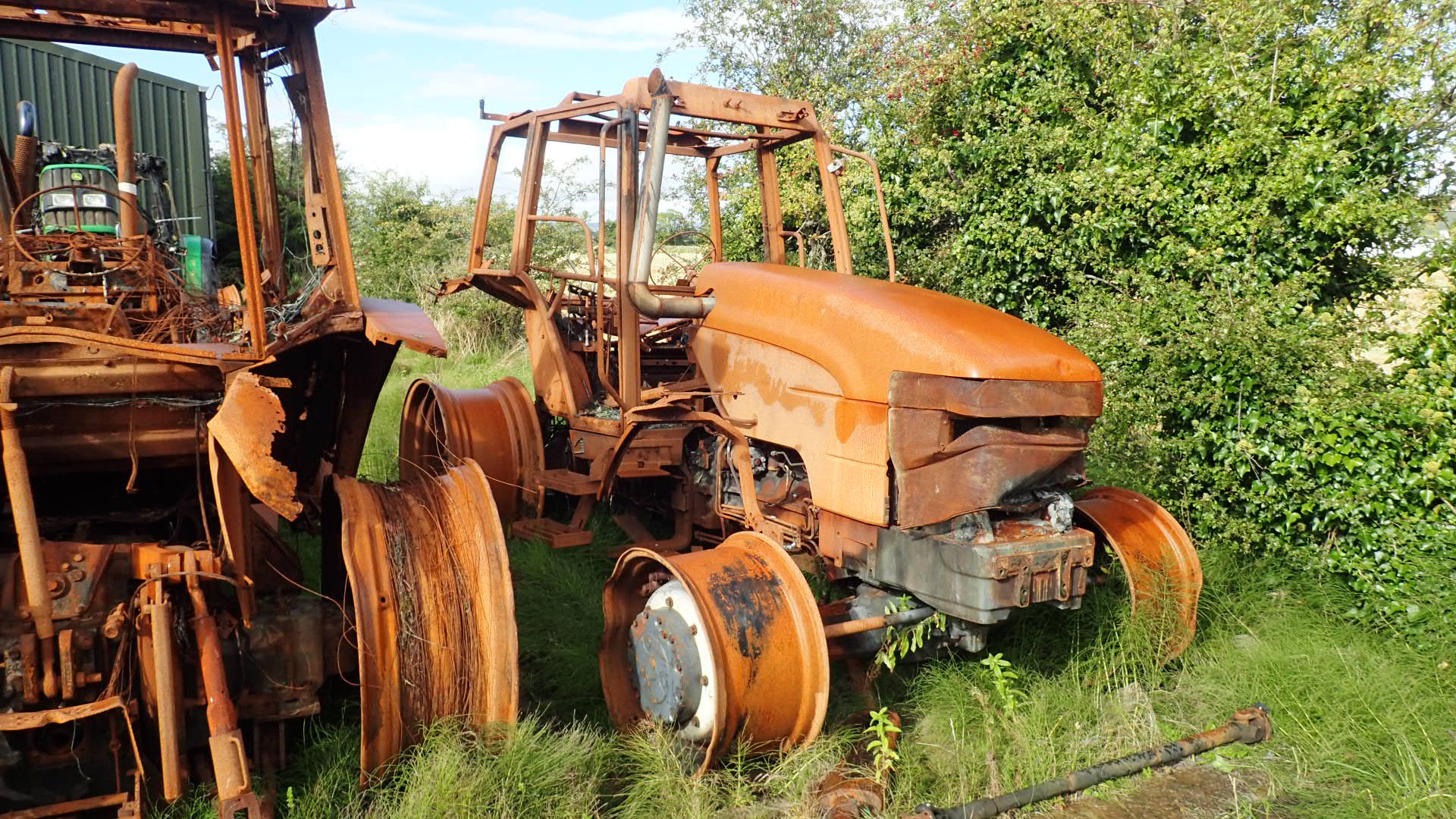
This is all well and good on paper but the prof, as they say is in the pudding. My project vehicle is a 1997 New Holland 8360 (The bigger one ;-)
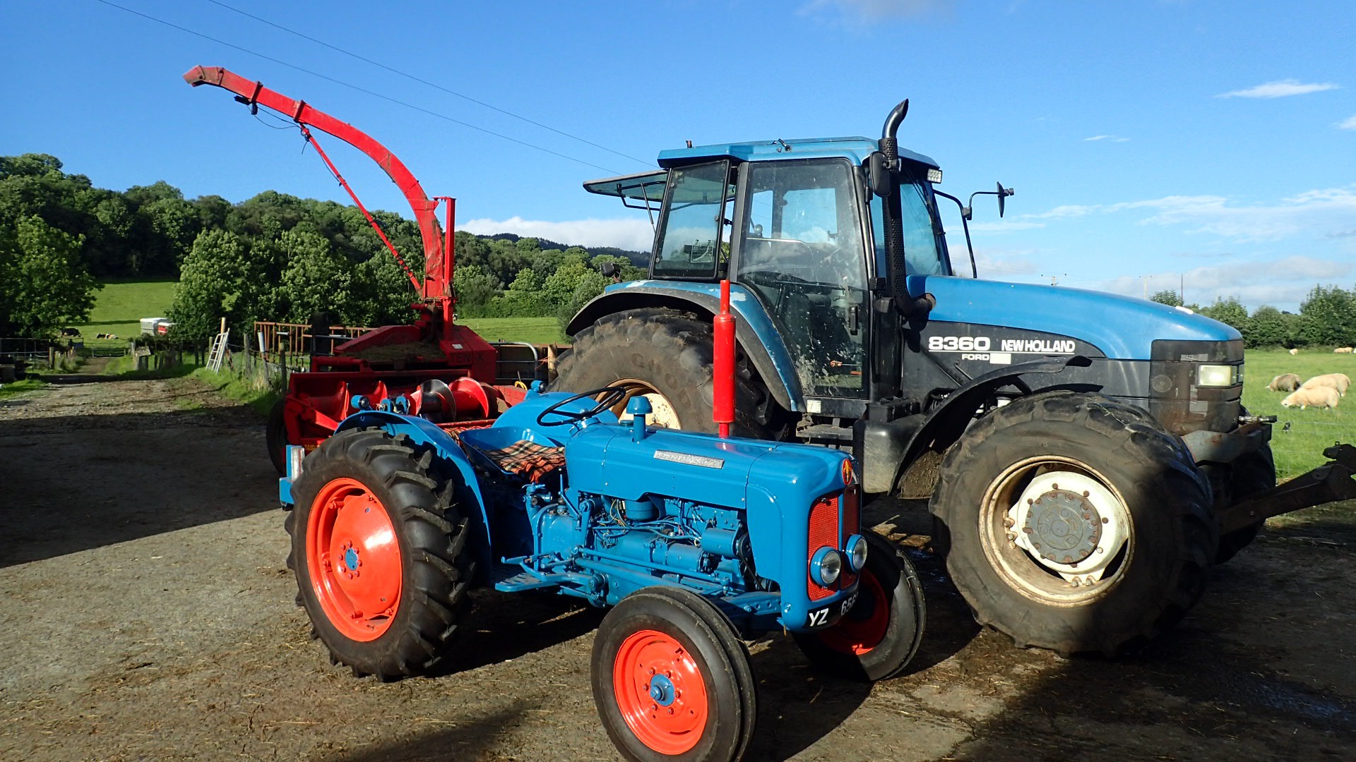
The smaller tractor was included for comparison, it's a 1958 Dexter still running well. The bigger 1997 New Holland ain't running so well. The wiring of the 1958 Dexter is a single A4 sheet of paper, there might be 20 wires in it, so it's a degree or two of complexity down from the 1997 New Holland. Even though the New Holland was designed and built a decade after the creation of CAN Bus, a more or less Open Standard it doesn't use that technology at all, relying on a multi-wire solution:
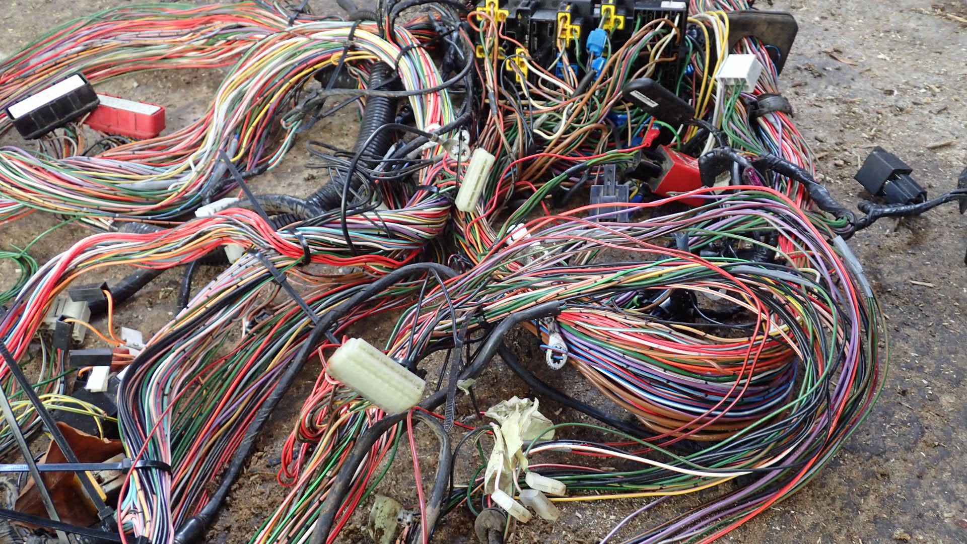
The above is most of the wiring loom, but by no means all of it. If the above mess was 100% reliable then there would be no problem and you might ask yourself why a farmer would let me loose on a 120BHP tractor. The thing is this solution is very complex, (takes much more then an A4 page to represent) and has deteriorated over time. Over the years the insulation on the coper wires has aged, hardened, and cracked of the conductor, resulting in a season of blown fuses. In that situation you let me loose, on the system ;-)
The wiring loom above can be very difficult to fault find. All these wires are normally encased in a further layer of insulation, so only the end connectors are exposed, and then they can be in hard to reach places in the tractor, requiring stripping parts off the tractor to reach them.
The above loom can be viewed as a mess of wires, which it certainly is, but it's also a network of information collection, power distribution and logic. That statement might require a bit of clarification. When I say information collection I'm talking about the various sensors and human inputs to the system. The position of a switch on or off is a piece of information, which is used by the system to change an output. At one level it's a switch and a connected light but at another level there is information being passed around the system. In some cases it might be more clearly understood as information where the input switches is not directly connected to the output, but is interconnected via a relay, which is more capable of conducting higher currents involved in some outputs. These relays act on the input information and distribute power to the outputs. You might have a wry smile at "power" but don't underestimate 12 Volts. The fuse box usually contains both the fuses in the system and relays responsible for distributing high current loads. The picture below is not the result of a fault in the system. No fuse blew, and all the wires involved would have been rated for the current load. In the case of the NH8360 two high current circuits were adjacent to each other. Each individually conducting would have been fine but when both were conducting the temperature of both effected each other.n The wires just got a bit hot and then a bit hotter over an extended period of time. Undoubtedly it was a hot day but the results are toasty:
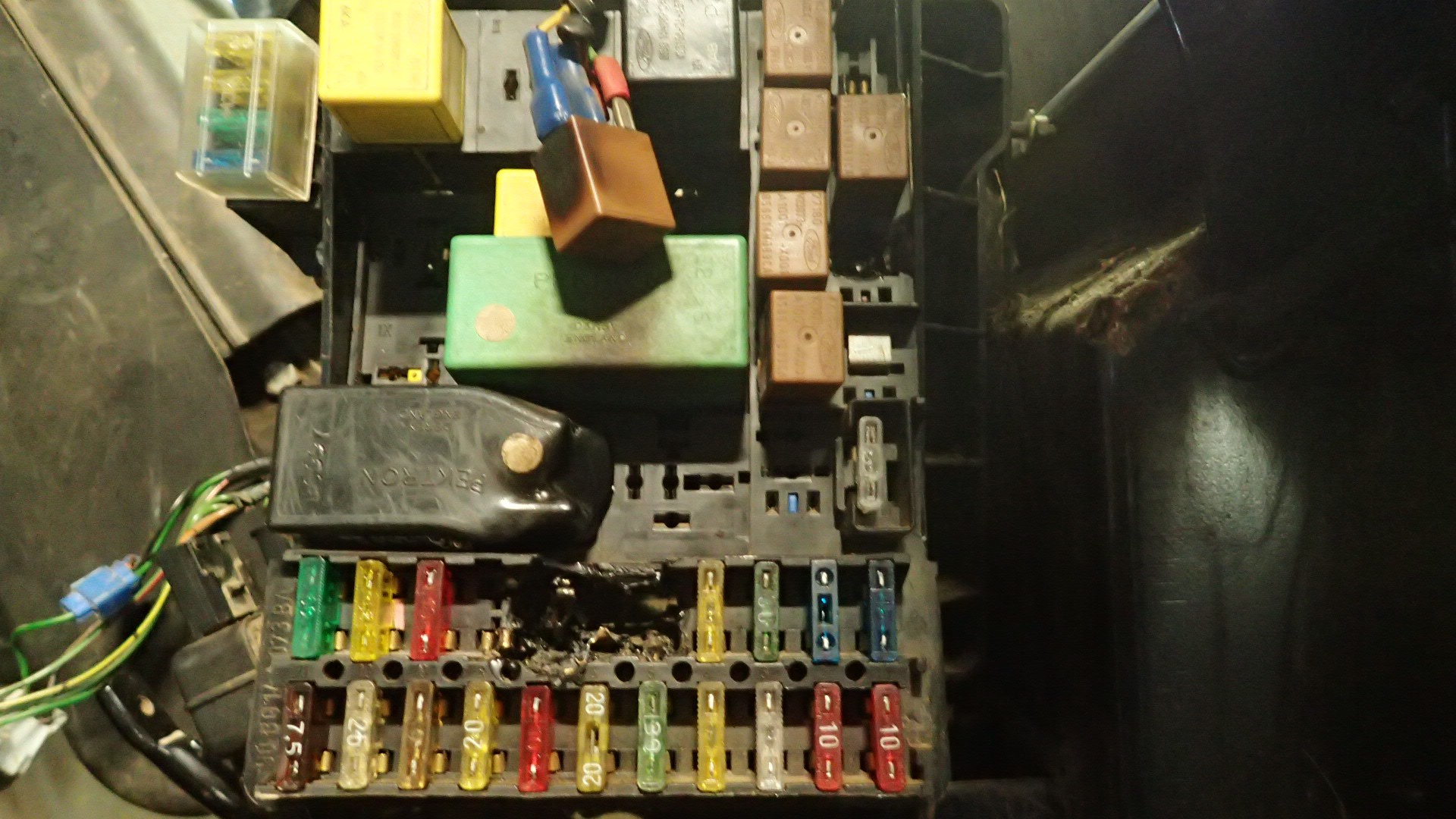
The above melted plastic and scorched relays may not appear to be too serious but the difference between the above picture and the one below might be as little as 10 minutes.
I took the above picture at an engineering place on the North Coast of Ireland, which specialises in buying these burnouts to salvage parts in the very heart of the system, which haven't been damaged. The above is another New Holland 8360.
I chatted one of the mechanics and he was saying that if there's still some unburned paint, on the engine block, it didn't get hot enough to melt the internals. As you can see on the above New Holland 8360 there's still a bit of grey paint in there. I asked Mr. Engineer if there was any correlation in burnouts between manufacturer, model and age of tractor but he said that they're all equally susceptible to a wiring fault which results in a burnout. He said he'd pulled 2 week old tractors out of a field totally burned out. All makes all models. In a country as small as Ireland he said they were pulling in about 2 burnouts a week in the summer season. Yeah 12 Volts is more then enough to ruin your day.
So back to the point there's Information and there's power but where's the logic. Well in the 1997 tractor there were two repositories for logic in the system. As you might imagine from the picture of the loom a lot of the logic is actually hard wired into the system. A switch might be directly connected to an output, if it's a low power load, or be hard-wired through a relay in the case of a high power load. In addition to the hard-wired logic there are a number of computers in the system:
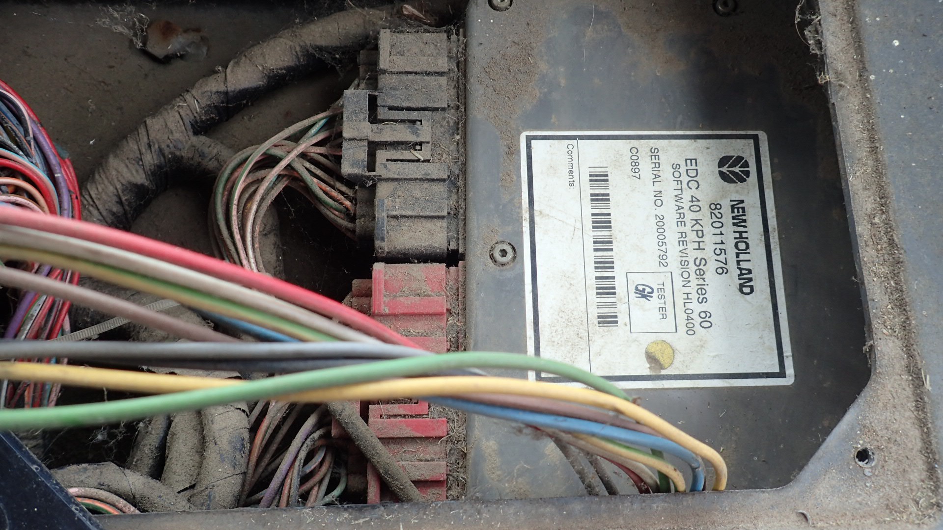
The above computer is 1997 vintage and has about 40 wires connecting it to the tractor. The computer is the Electronic Draft Control EDC Computer, only responsible for lifting and lowering the lift arms at the rear of the tractor. What happens when this computer, no longer produced, fails? A farmer will find himself with a mechanically sound 120 BHP tractor, which is unfit for purpose because of the logic tied up in that dead computer.
The funny thing is that the logic tied up in that box is something which a modern day teenage maker would have no problem tackling. I'll outline the logic just to give you a laugh. In the 1958 Dexter pictured above there was a lever on the right hand side of the seat. That lever, still in same place until recently, controls the lift arms at the rear of the tractor. (You can see two lift arms on the front of the New Holland 8360 above, not the burnout, which didn't have front lift arms.) So you have a lever and two lift arms for raising and lowering an implement attached to the rear of the tractor. Lower the lever all the way down and the lift arms hydraulically lower the lift arms and thus the attached implement. Raise the lever, by your seat, and the arms raise accordingly. Half way up is half way up etc. etc. In the case of the 1958 Dexter there was a mechanical linkage between the lever and the hydraulic lift pump.
So moving to the 1997 New Holland the mechanical linkage between the lever and the lift arms has been replaced with some electronics and a computer. In this case the lever is attached to a simple Potentiometer which divides a 5V signal from the computer. So the Potentiometer sends a voltage 0V - 5V to the computer. 0V might signify fully up or down and 2.5V is lift arms in the middle of their travel. In addition to the Pot on the lever there's another on the lift arms doing exactly the same thing. It measures the current position of the arms and feeds the information to the computer. To complete the picture the computer calculates what it should do and sends a PWM output signal to one of two electronic valves connected to the hydraulic lift pump. That's it, it's that simple. A tractor could be brought to its knees by the simplest logic device. So a driver raises the lever and changes an input to the Computer which has another piece of information, the current position of the lift arms. Given a difference in the two inputs the computer drives one of two outputs to set the requested position of the lift arms. Rocket science it ain't.
There's slightly more to this computer's logic. The computer needs to be able to calibrate the potentiometer on the lift arms. Down is easy as when the computer removes pressure from the lift pump gravity will take over and lower the lift arms to their extreme position. The highest position is a tad more complicated though. Replacement potentiometers won't all be exactly the same and if the hydraulic lift pump tries to apply pressure beyond the mechanical limits of the lift arms then it will either damage the hydraulic system or the mechanical system. So the computer has a configuration setting which you enter on power up of the system. You have to disconnect the lift arms from the hydraulic lift pump and apply throttle to the tractor to raise its engine revs to about 1,000 rpm (from memory). Every computer in the New Holland 8360 receives another crucial piece of information from the tractor's alternator, which generates the electricity to charge the batteries and run the system. The alternator outputs a square wave which is directly proportional to the engine speed. This square wave, representing engine speed, is fed into all four computers in the system. When you are in the lift pump configuration mode the operator has to lower the lever to it's lowest position which the computer takes note of, storing it in battery backed RAM (No persistent storage in the system). Now when the operator raises the level to its highest position the computer, in configuration mode, assumes you've set the lever to the highest position and starts to apply hydraulic pressure to the lift pump. Once the lift pump reaches its mechanical limit it will be pressing against an immovable object and will cause the engine speed (revs) to drop, as the engine struggles to fight against the immovable object. The computer now knows where the mechanical limit is and what the reading from the potentiometer on the lift arms would read at that limit. Again it's not too complicated.
For completeness sake I should include one more piece of information and element of logic. Manufacturers are always trying to find some edge which will give them some advantage over their competitors in the race for customer's money. For whatever reason in agriculture the ability of a tractor to plough has always been a yardstick.
Back in 1997 humans were still the creators of logic, machines learning was still years away. Back in the era of the Dexter tractor if a farmer was plouging a field and the plough, being pulled through the soil, hit an underground obstacle, (a large stone, or the root of a tree for example), then the forward progress of the tractor would be halted and the tractor's driving wheels would simply spin on the spot, digging into the ground. In this situation the farmer would simply raise up the plough, (using the magical lever by his/her right hand side), when the plough had been raised enough to clear the obstacle forward progress would resume and the farmer could again lower the plough deeper into the soil, to resume normal ploughing. That's not complicated logic. Hit an obstacle, briefly raise the plough. In the race for customers and some perceived edge New Holland put a radar system into the NH8360 to detect forward motion of the tractor. The tractor also has information about the rotation of the driving wheels of the tractor and from these two pieces of information can determine that whilst the wheels are moving there is no forward progress. The EDC Computer can in 1997 automatically raise the lift arms at the rear of the tractor. It's the small things.
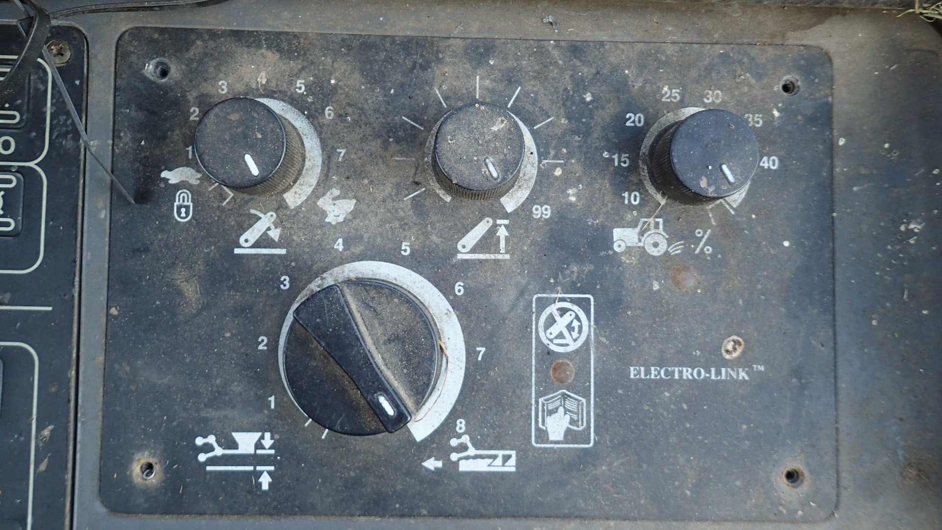
Another feature is the addition of a collection of four Potentiometers which can adjust various settings in the EDC Computer. So the responsive speed of the EDC to human input. One Pot will set the maximum height of the lift arms, so that when you lift a high implement, like a hedge cutter, you don't put that implement through the rear window of the tractor. Back in Dexter era the farmer would just have to be careful.
To be honest I don't think that the family NH8360 has ever done any ploughing in it's life and rather then using extra input controls the operator is still expected to be careful. The four additional potentiometers have never been used. Expensive unused logic but can we replace it if required?