 ivorivetta
Overall system:
Here are all the core components laid out for this log update, some are drawn in because I did not have them on-hand
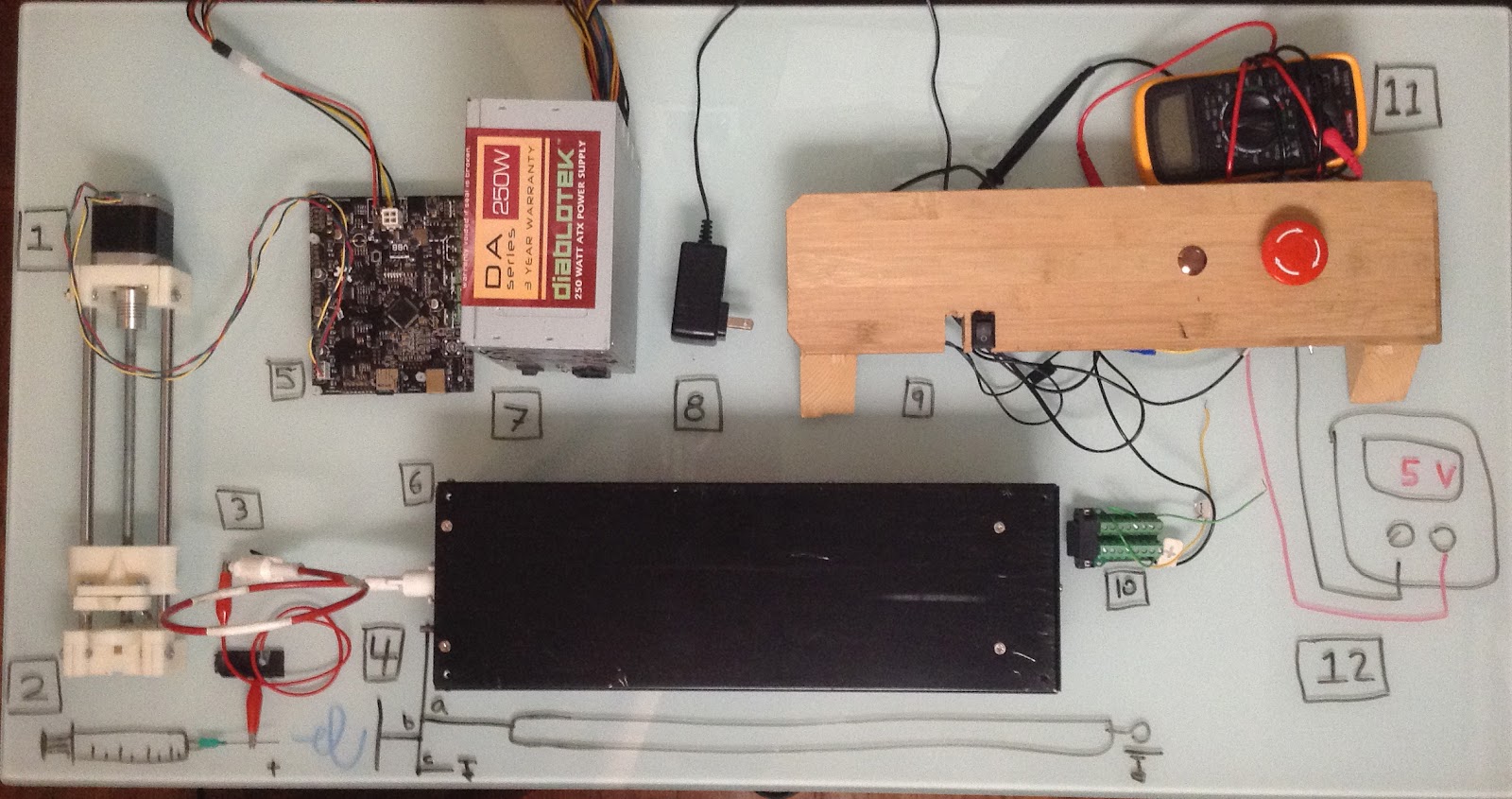
1 - Syringe pump
2 - Syringe (Drawn in) with needle tip.
3 - HV cable with alligator clip. In practice, this takes some finessing to avoid unnecessary cable length. Could affect your electric field if you let it too.
4a - The ground cable for the chicken stick
4b - The ground cable for the collector
4c - HV best practices use an actual earth ground for circuit ground. In this low current scenario, I just grounded to a chassis.
5 - Smoothieboard - The brains of it all, overkill for this project but it’s just so easy to work with and what I had available
6 - HV power supply - The mysterious Bertan 2554
7 - A standard PC power supply supplied the Smoothieboard 12V
8 - 24V source - The input voltage the HV power supply needs. Since it was a low current application, I floated a 12V wall outlet off of the 12V rail of the ATX. Hack forsure but convinced myself there wasn’t any ripple or other weird effects with an oscilloscope.
9 - The switches - Had three total: 1 to power up, 1 to enable output and 1 E-stop to cut power
10 - The DB15 to terminal adapter
11 - Multimeter or Oscilloscope wired to the Voltage monitor pin of the power supply
12 - Variable power supply wired to the voltage set pin. 0-10VDC input maps to 0-30kV output
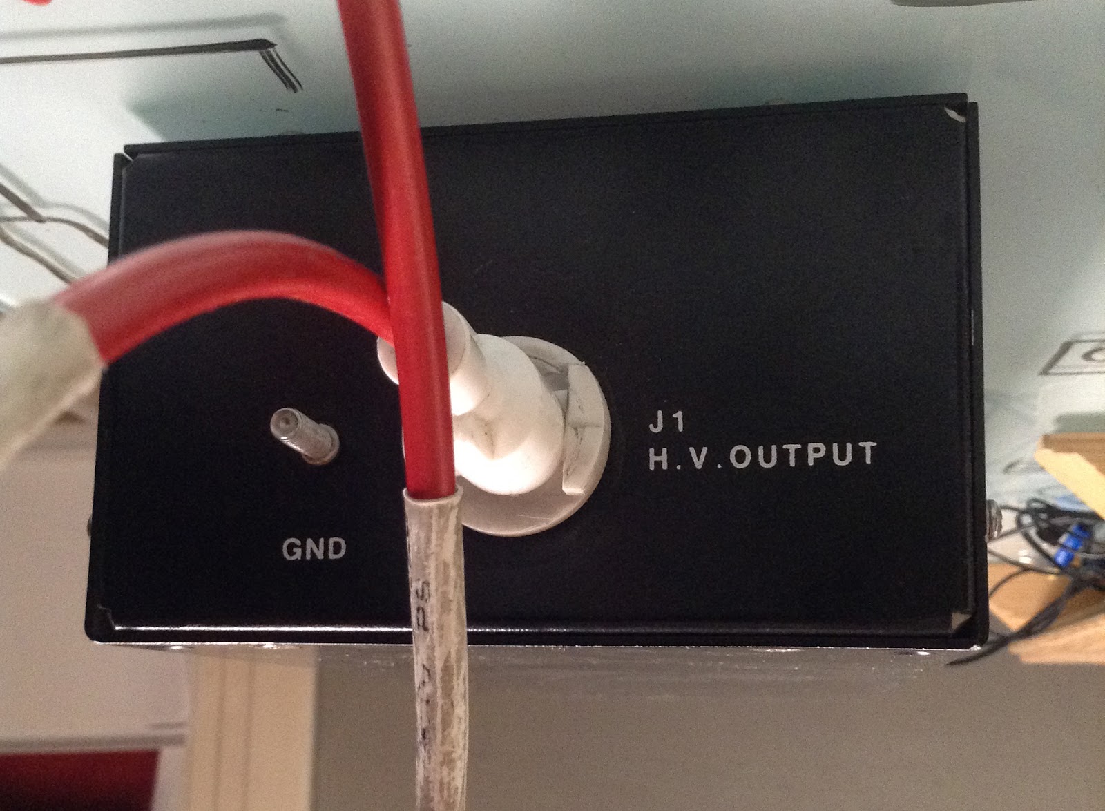
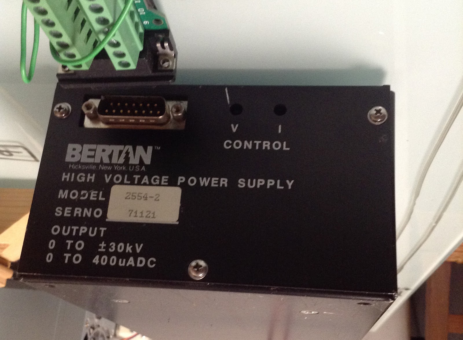
And some detail shots of the power supply.
The front panel hosts the HV output and ground return path. This is a good look at the custom cable built for this power supply. The white plastic twist lock connector also has a slip ring that lets it rotate w/o binding or breaking. The ground connector has a 10-24 thread that makes it simple to lock down with the appropriate nut.
Back panel has the DB15 breakout for access to enable and voltage set pins among others. If you jump the “local control” pins (1 & 3) with their respective remote control pins (2 & 4), you can set the control voltage and current with the potentiometers accessed through the V and I holes.
Discussions
Become a Hackaday.io Member
Create an account to leave a comment. Already have an account? Log In.