ivorivetta
-
Hello fibers
07/11/2016 at 10:37 • 0 commentsThe first fibers!
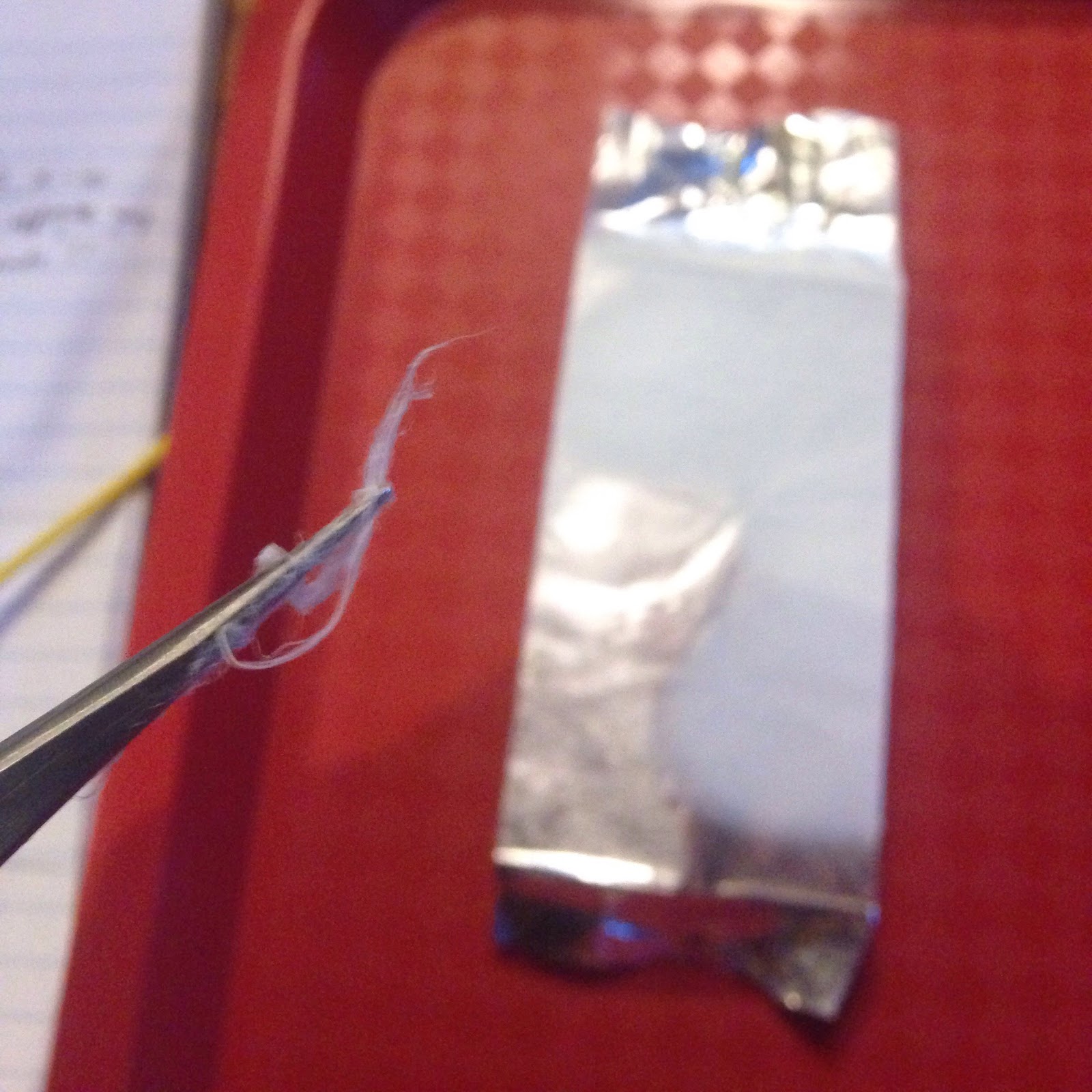
Achieving fiber formation took a couple tries. The first hurdle was drawing fibers out thin and far enough so the solvent could evaporate completely from the thread by the time it landed. If solvent accumulated on the collector, it would redissolve the fibers into a film.
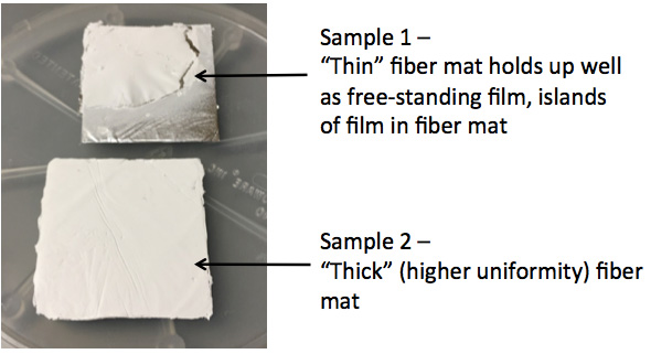
Trial and error took us from sample 1 which consisted of fiber and film islands to sample 2 which was all fiber.
You’ll notice the collectors are now somewhat standardized to promote reproducibility. Surface area is one of the many variables to manage in order to compare test results from one trial to the next.
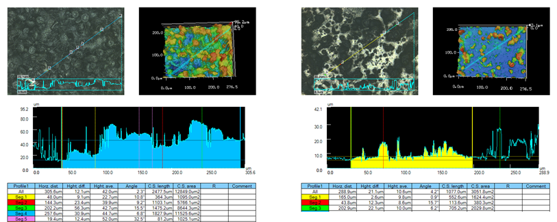
Now that our samples pass visual inspection, it’s time to review them under a more powerful lens, an optical profilometer if I’m not mistaken.
In sample 1, we can take a look at the splatter zones and note the absence of fibers. The top left grayscale image is the best visual and just shows blotchy accumulations.
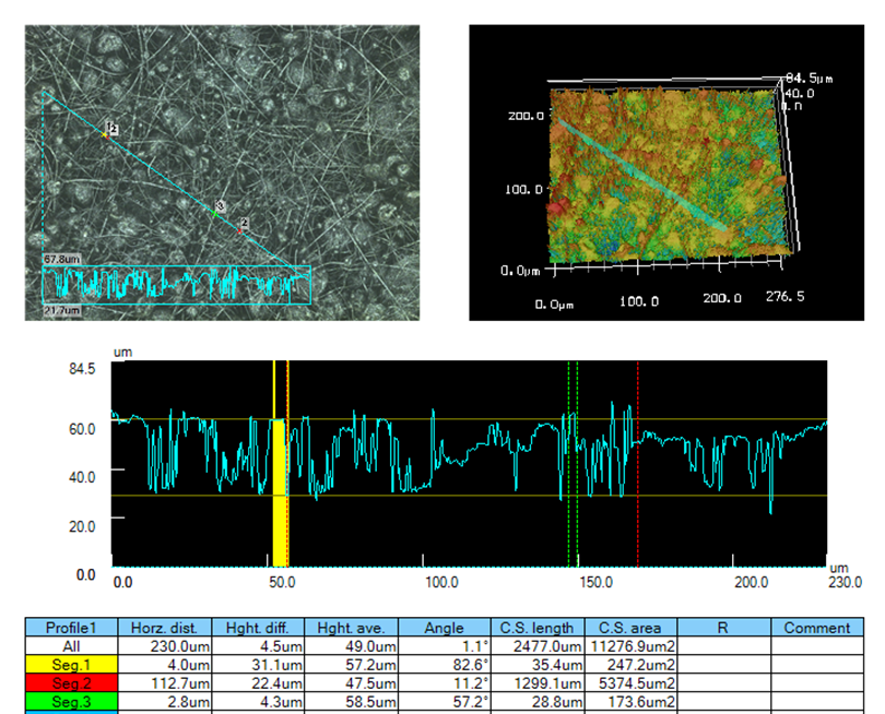
The data for sample 2 looks much more promising. The top left grayscale image has prominent fiber formation, albeit littered with defects.
Look at all those globules! We’re looking for clean uniform fibers without beads.
There are some more experiments to run and parameters to refine. But this was a fun first development cycle!
With the foundation laid, a round of production and testing can turn around in two weeks. That’s a respectable cadence for a side project, especially considering ~5 days of that is just shipping and logistics between production in San Francisco and testing in Baltimore.
Stay tuned. -
Characterizing the system
07/11/2016 at 09:50 • 0 commentsHV power supply - Characterization
Measuring the linearity of a power supply deserves its own post and they’re out there. In this case, I was only worried about how linear the mapping was from 10-20kV. With a well engineered supply like this, I confirmed that the linearity in the middle of the output range was a non-issue. This HaD Arksen post covers some of the other voltage spikes and ripples I checked for in my HV output. Luckily, any transient signals I was worried about were smoothed out by the control electronics inside.
The article also accurately describes the quality of the Arksen variable power supply I was using to set the control voltage from 0-10V. The most inaccurate link in my system was actually the display on the Arksen which was off by 10% at times! From then on, I always had a Multimeter in parallel to display the “true” input voltage
Syringe pump calibration
Before getting into fluid units, I followed the same process as calibrating a 3D printer axis to lock down the linear dimensions. I jogged the syringe pump 10 steps and measured the distance in mm. Took this measurement 3-5 times and updated the conversion factor already in the machine. Then I did the same with 50 step increments to refine the measurement.
Ideally when I jog a unit of one in my printer software, I would like it to be 1ml. This would make any flow-rate math simpler in the future. The easiest route was to measure the graduation markings on the syringe. It can be argued whether or not this is the most precise and accurate method but I told myself to worry about if it stopped me from producing fibers.
I could have tried something like extruding a volume of water and measuring its mass but I did not spend enough money on a scale to trust any gained accuracy. Disposable syringes have a rubber seal which can tend to be somewhat jerky (hysteresis) and this limits the precision I can hope to achieve. Glass on glass syringes are precision ground and what you use when you need smooth motion in your pump. I think they’re used to handle higher pressures for life science applications too?
In the end, it didn’t stop the show
-
Pulling it all together
07/11/2016 at 09:45 • 0 commentsOverall system:
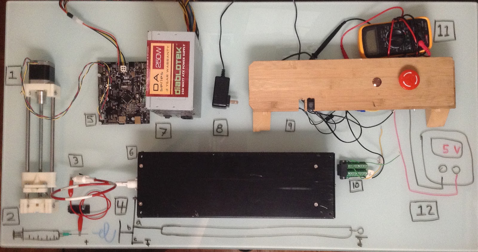
Here are all the core components laid out for this log update, some are drawn in because I did not have them on-hand
1 - Syringe pump2 - Syringe (Drawn in) with needle tip.
3 - HV cable with alligator clip. In practice, this takes some finessing to avoid unnecessary cable length. Could affect your electric field if you let it too.
4a - The ground cable for the chicken stick
4b - The ground cable for the collector
4c - HV best practices use an actual earth ground for circuit ground. In this low current scenario, I just grounded to a chassis.
5 - Smoothieboard - The brains of it all, overkill for this project but it’s just so easy to work with and what I had available
6 - HV power supply - The mysterious Bertan 2554
7 - A standard PC power supply supplied the Smoothieboard 12V
8 - 24V source - The input voltage the HV power supply needs. Since it was a low current application, I floated a 12V wall outlet off of the 12V rail of the ATX. Hack forsure but convinced myself there wasn’t any ripple or other weird effects with an oscilloscope.
9 - The switches - Had three total: 1 to power up, 1 to enable output and 1 E-stop to cut power
10 - The DB15 to terminal adapter
11 - Multimeter or Oscilloscope wired to the Voltage monitor pin of the power supply
12 - Variable power supply wired to the voltage set pin. 0-10VDC input maps to 0-30kV output
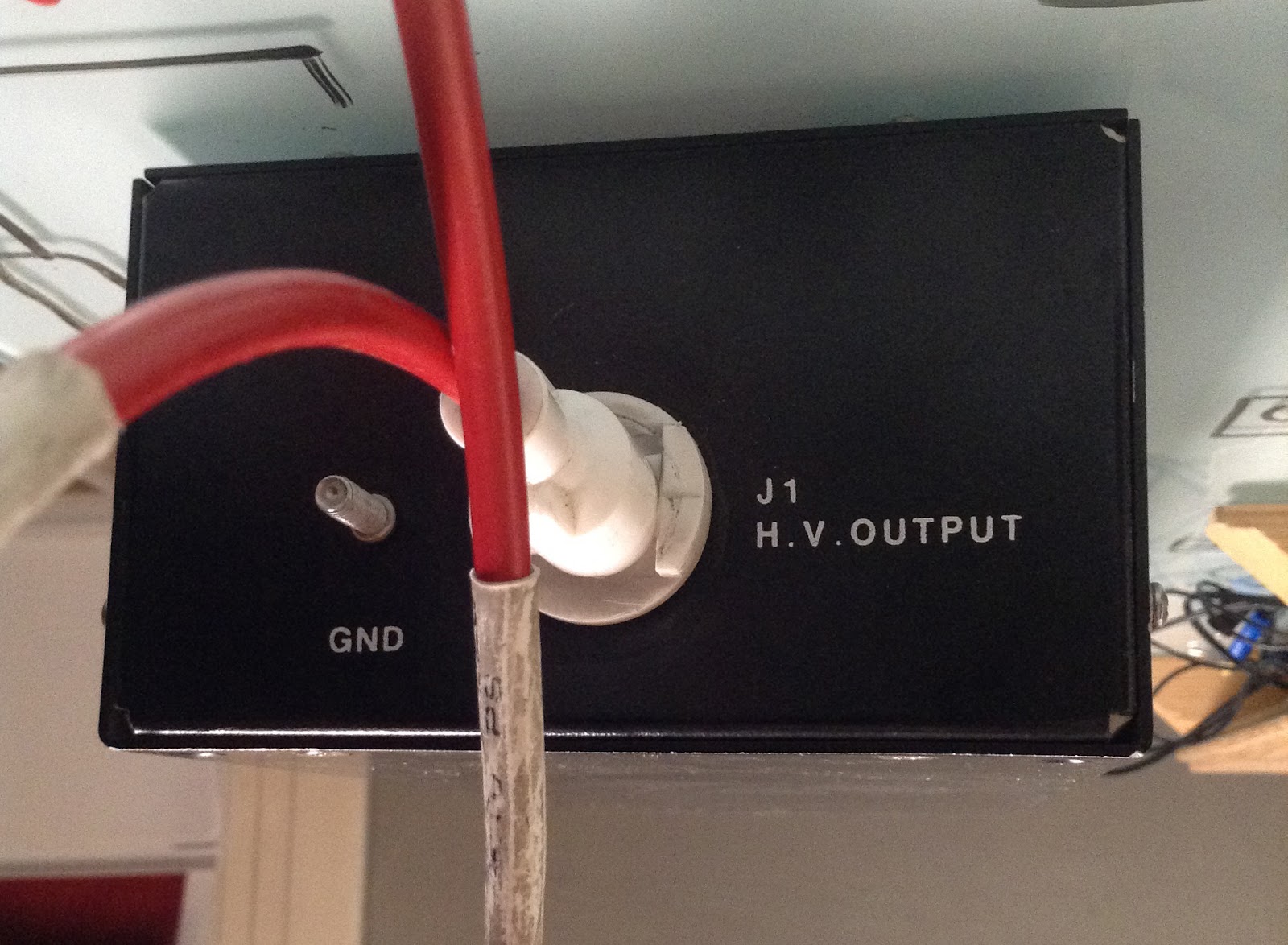
And some detail shots of the power supply.
The front panel hosts the HV output and ground return path. This is a good look at the custom cable built for this power supply. The white plastic twist lock connector also has a slip ring that lets it rotate w/o binding or breaking. The ground connector has a 10-24 thread that makes it simple to lock down with the appropriate nut.
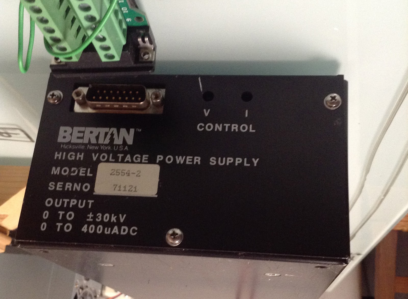
Back panel has the DB15 breakout for access to enable and voltage set pins among others. If you jump the “local control” pins (1 & 3) with their respective remote control pins (2 & 4), you can set the control voltage and current with the potentiometers accessed through the V and I holes.
-
Research and sourcing
07/11/2016 at 08:57 • 2 commentsBackground research -
I first started hopping around Google Scholar to see what people were up to, and for how long. The earliest invention is in 1887, with interesting devices and applications published on a monthly if not weekly basis in present day. On the web, www.electrospintech.com became a heavily used resource. It was humbling for what I thought was a novel and clever invention of mine to already have an article written up, great email newsletter too. With these two resources, I was able to pull most of the operating parameters I needed to inform the rest of these builds.
Sourcing -
From previous experience, I knew that the syringe pump and power supply were going to be the two big budget items. Buying solvents for home delivery is a pain sometimes too. Let’s get into it:
Fluidics
Syringe Pumps can easily get to $200+ for lab applications. Open source community and 3D printing to the rescue! Using this design as my base, I shed any components for retracting the syringe pump to keep things simple since I only need to push during processing/fabrication. Running multiple trials gets tedious quickly so easily resetting the pump between spins was a priority, and I thought manually doing this was fine. Having less clamps helped with that too.
I had spare linear rails, threaded rods, and stepper motors, along with a smoothieboard for the brains. It came together nicely after some tweaking in OpenSCAD to fit my syringes and some reaming to account for my 3D printer tolerances. Some blunt needle tips rounded out the fluidic system. I’ll mention calibration in a future post.
Electronics
The High Voltage Power Supply is another item that could easily cost $3k+. Low quality power supply units (PSU) have caused me hours of debugging headaches, if not destroying entire experiments, in the past.
There are enough variables in electrospinning to control already, plus adjustable range and positive/negative voltage options would be awesome capabilities to have considering this is a process development exercise. eBay, you’re amazing:
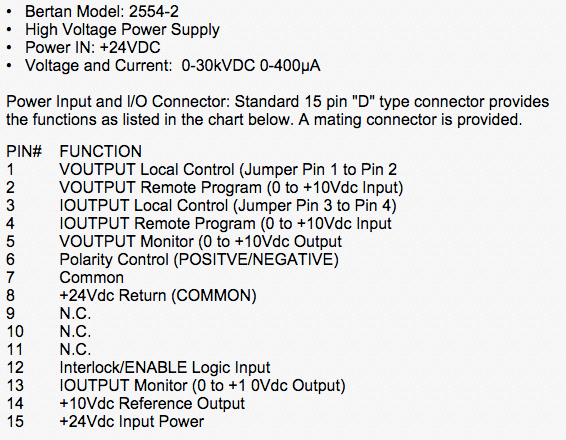
What a deal! Plus the guy had an extra so I went ahead and got two. The tradeoff? This power supply is salvaged from an old spectrometer and I’m buying as-is. I’m nervous it won’t work. The extra fun bit? This Bertan company was acquired years ago and no documentation exists besides this little clipping of the pinout:
Tl;dr: Slightly sketchy but I got it working. I’ll do a bonus post later to show off the insides and some of the reverse engineering steps I took to validate this pinout.
High voltage wires are also highly specialized. This one had a very specific connector at the HV output. After I found out what spectrometer this power supply came from, I called up all the listed repair and technician vendors I could find on the west coast. No luck. Looking eastwards, a shop in Texas had some on stock and I bought up the three they had on hand. Cost more than one of the power supplies but equally as essential.
Aluminum foil was the collector of choice to spin on with alligator clips connecting most of the components. Grounding cables for earth ground and the chicken stick are from repurposed extension cords. I polished all the connection points and used conductive grease to keep any capacitive charges from building up in my system as a preventative measure. A DB15 to wire terminal adapter made it easy to interface with the power supply.
Wetware and Enclosure
Hadn’t set-up a wet lab at my home shop before but I knew some sacrifices would have to be made compared to labs I’ve worked at in the past. Was able to find centrifuge tubes for mixing and a scale for measuring easily enough on Amazon. Graduated cylinders, gloves, stir rods too. Already had protective eyewear at home.
Ventilation is absolutely paramount as the solvents that are evaporating are very strong! Nothing extremely carcinogenic but didn’t want to push my luck. My initial hacked together fume-hood used computer fans to push the air through activated carbon. Filtered the air well enough but was too much inconvenience to put into practice. In the end, I bit the bullet and did these experiments outside in a covered patio. I monitored humidity and pressure and in the end, it all worked out fine, I guess if you consider your “system” and “environment” appropriately/sufficiently.
The enclosure was just the biggest plastic storage container I could fit in my car. Didn’t run into any trouble there and drilled into it freely to run the grounding cables and syringe tip + HV cable.
eSpinTech, again, has a great starter guide. Apparently PVP and PEO are two plastics that spin easily. I instead opted for PolyStyrene as a standard material to learn from. I was able to find some detailed papers that had some great parameter experiments I could replicate. It also meant I could use waste Styrofoam and explore the up-cycling potential of our processes. Future project! I was luckily also able to secure a suitable solvent from Amazon, Dimethylformamide (DMF), that dissolved the plastic like a dream, so instantly and to a large concentration with high solubility.
Electrospinning functional fibers
eSpinning process and build development