 jellmeister
I have been beavering away at the munching engine since my last update.
I have worked up the concept of using pinch belts mentioned previously and prototyped it with some success.
Explanation of the concept:

The idea is pretty simple. Two grippy silicone belts running between two pairs of rollers. They are pinched together at the business end such that any grass long enough to reach the pinch point gets its top torn off, and then the top is conveyed up the belts to a hopper that collects the cuttings. I was worried that this might just uproot the plant rather than trimming the top but I did a quick test running a silicone band between two whiteboard markers and even on a damp day it didn't uproot any grass. I might supervise the robot for a few weekends though, just in case...
Ordering and 3D printing parts for the prototype
I looked around for silicone belts online and found amazon sell 1" wide bands that are 12" laid flat double (24" circumferential length) LINK. While these are narrower than I hoped, they £15 for 10 and next day free on prime. The downside is this is a multicolour pack so the prototype is COLOURFUL!!
I also ordered some 26x10x8 bearings and a 5RPM 12V 1W motor, which also arrived next day.
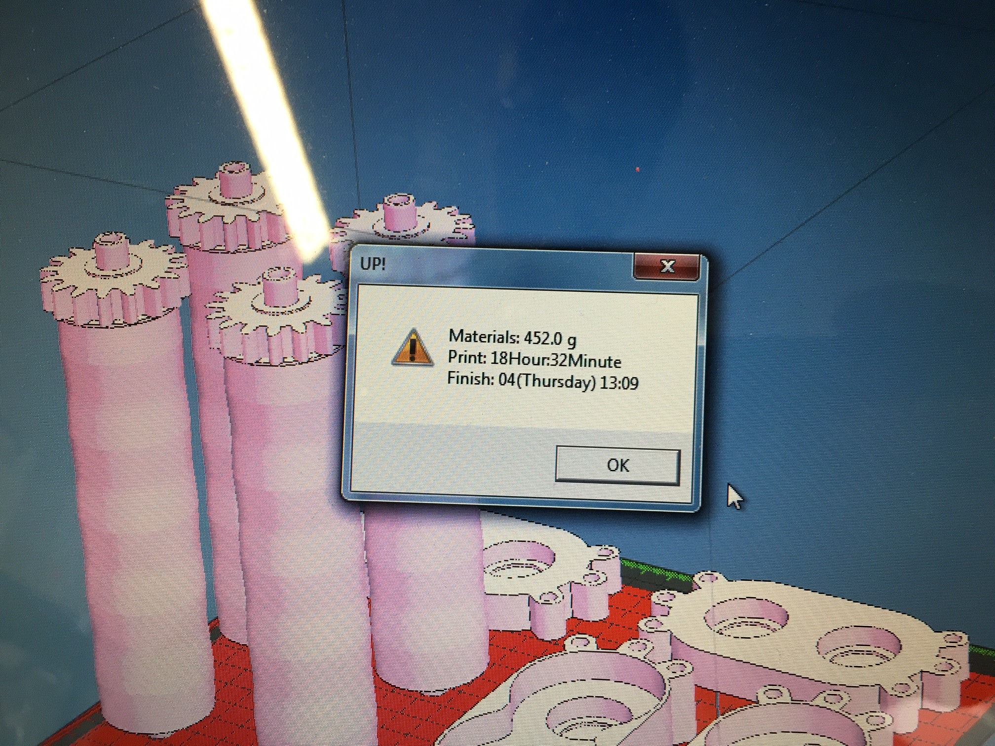
I designed the front rollers and end caps to house the bearings and hold the rollers together as well as holding the motor. I 3D printed two copies of the set to save design time, although it emerged that the print was huge, using half a kilo of filament and taking 18 hours! Given the rear rollers will need redoing this was a little wasteful in hindsight, but at least I have a spare set now and I was keen to make progress.
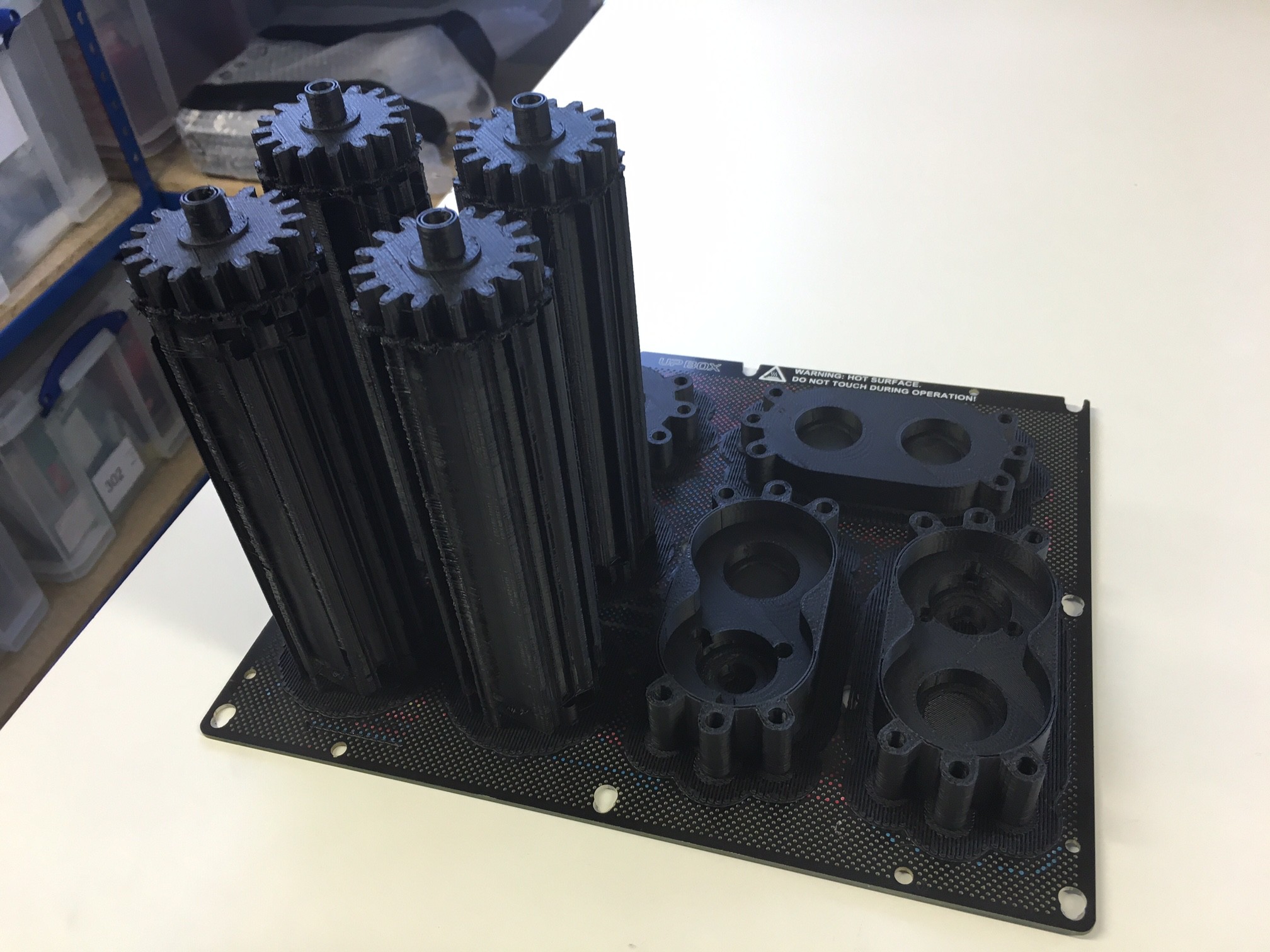
From this view you can see the part designs. 4 rollers that fit into bearings both ends and gear together one end (the actual surface of the rollers is behind the support material but can be seen on the previous image in cad. Note the rollers taper in and out, this is to guide the belts as they will naturally centre on the widest parts (in theory anyway!). The gear end of the rollers has a hollow shaft that has a D profile internally to engage the motor shaft (more on this later).
The near right parts cover the gears around the edge, an house the two bearings as well as giving counterbored holes for screwing the motor on.
The far parts just house two bearings. All bearings are a tight sliding/loose press fit engagement.
When I designed the bearing housing end caps (both types) I hadn't thought anything through further so just added 3 bosses each end for later attachment.
Assembling the prototype
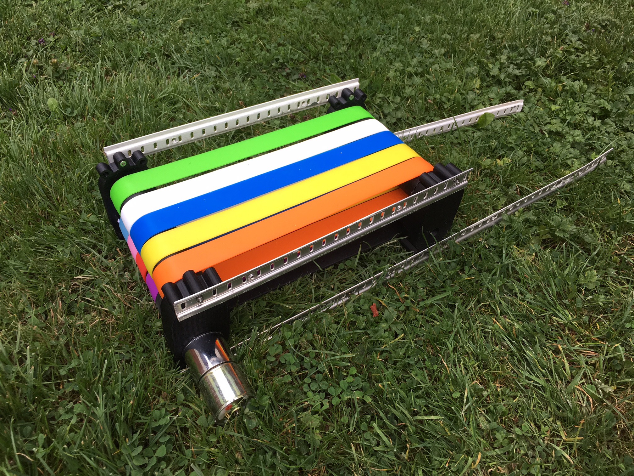
See what I mean about colourful?
Like a numpty I forgot to photograph the assembly but it was pretty simple and is described below:
Pressing the bearings into the housings was done by hand, using relatively high force but is only possible when they are in square so needed careful pushing evenly from both sides.
The motor screw hole PCD was luckily exactly wide enough for the M3 screw heads to fit outside the bearing, really important as making the shaft of the roller longer at 10mm diameter to fit the motor behind the bearing would likely cause it to break. Screwing the motor on was easy enough.
I then put 5 bands around each of the front rollers and pushed the into the bearings. I did the motor side first as the D shaft needed lining up. Inserting the other end required the shafts to be squeezed firmly together but wasn't two hard.
I repeated the process for the back end, being careful not to cross any of the belts, and the lack of motor made the assembly much simpler.
At this point I had two pinch roller assemblies attached by a number of belts. I wanted to quickly and simply align and separate these to tension the belts for initial testing so I raided my shed for some old shelf stripping. Screwing one end of the four lengths was easy enough, but I needed assistance from a friend to hold the rollers parallel as I tensioned the belts because when only one side is parted the belt tension applies excessive bending to where the roller shafts leave the bearings.
Once all four strips were screwed on both ends the assembly was complete. The rollers can pivot to be a parallelogram like the concept sketch, but for ease of use I kept them square. It should also be noted that the only thing holding the bearing housings on the rollers is the fit of the bearings (luckily I have got experienced at press fits on UP 3D printed parts). I plan to add some m5 threaded bar when I have some to tie them together.
Bench testing
I powered the motor with 12V from a lab pack and despite the resistance of the compressed belts between the rollers, it ran happily and the current was a similar 0.08A to the free running current. The gear ratio is so high that the torque at the shaft is insignificant compared to the gearbox friction. Firmly holding against the motor took the current to 0.10A but I couldn't stop the roller without risking getting my finger pinched.
Next log will discuss lawn tests :)
Discussions
Become a Hackaday.io Member
Create an account to leave a comment. Already have an account? Log In.