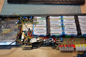
Starting with some 18650 batteries my son had given me, I decided to design a BT beacon that would use them.
0%
0%
A Beacon Battery System
A low cost smart battery for Bluetooth Beacons
Become a Hackaday.io member
Already have an account? Log in.
Just one more thing
To make the experience fit your profile, pick a username and tell us what interests you.
Pick an awesome username
hackaday.io/
Your profile's URL: hackaday.io/username. Max 25 alphanumeric characters.
Pick a few interests
Projects that share your interests
People that share your interests
 Enki
Enki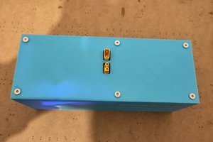
 AIB
AIB
 Kumar, Abhishek
 Paul Andrews