The VederPSU is a small and efficient lab power supply. Some of the requirements are:
- Small, less then 10*10*5cm in size
- Because of the size limitations, the VederPSU needs to be efficient as there is no space for a big heatsink
- 0 to 30V output.
- 0-2A output
- Low noise (less then 30mV)
- Usable standalone and PC controlled
Current status:
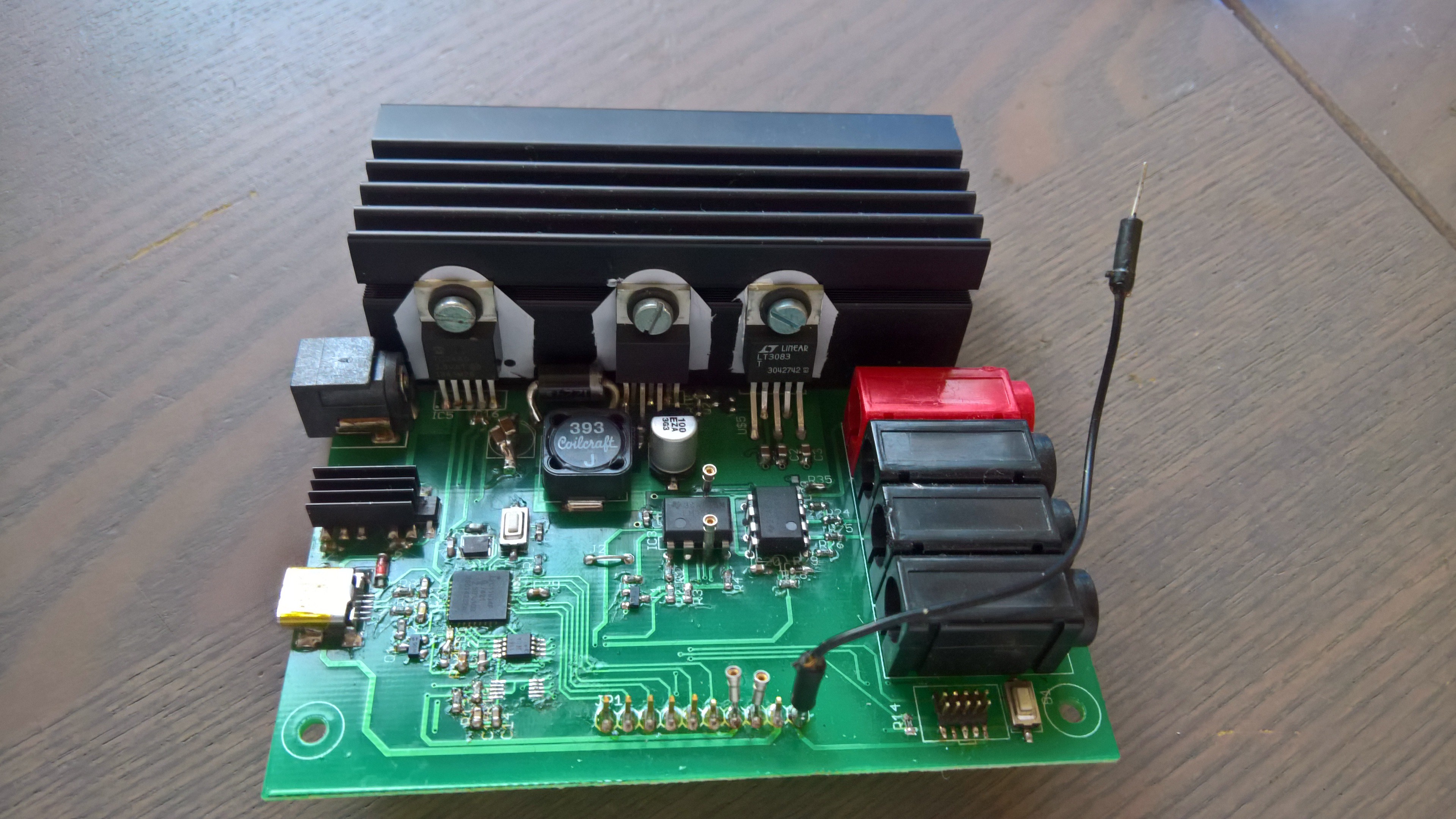
Hardware works apart from the following bugs:
- LT3081's don't regulate fully to 0V, a negative supply is needed to fix this issue
- 2 grounds not connected in schematic, this requires 2 bugwires to fix.
- The current 5V regulator has a maximum input of 20V, which is a problem with a 24 to 36V input it can get..


 Nathaniel VerLee
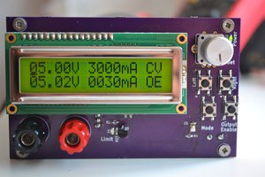
 Elia
Elia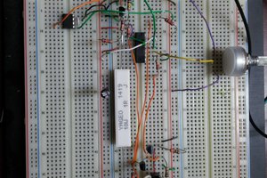
 Marc-O.
 gokux
gokux
Love it! Have you considered using the LT3091 as well, to create a +/- power supply? : )
Would you mind sharing the code as well?