 Simon Merrett
I have found a few points of light, mostly around the lone via which gives out a sine wave when the laser is firing. Initially, I assumed this was some ramp-esque control signal to the laser but the photos below suggest that it's actually the output from the laser receiver (and it's conditioning circuitry) into the microcontroller. The first photo is of the pad/via in the bottom right hand corner of the photo.
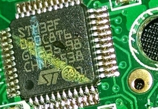
When I checked, this is connected to pin 11, PA1 on the LFQP 48 package and the additional function of that pin is... ADC_IN1.
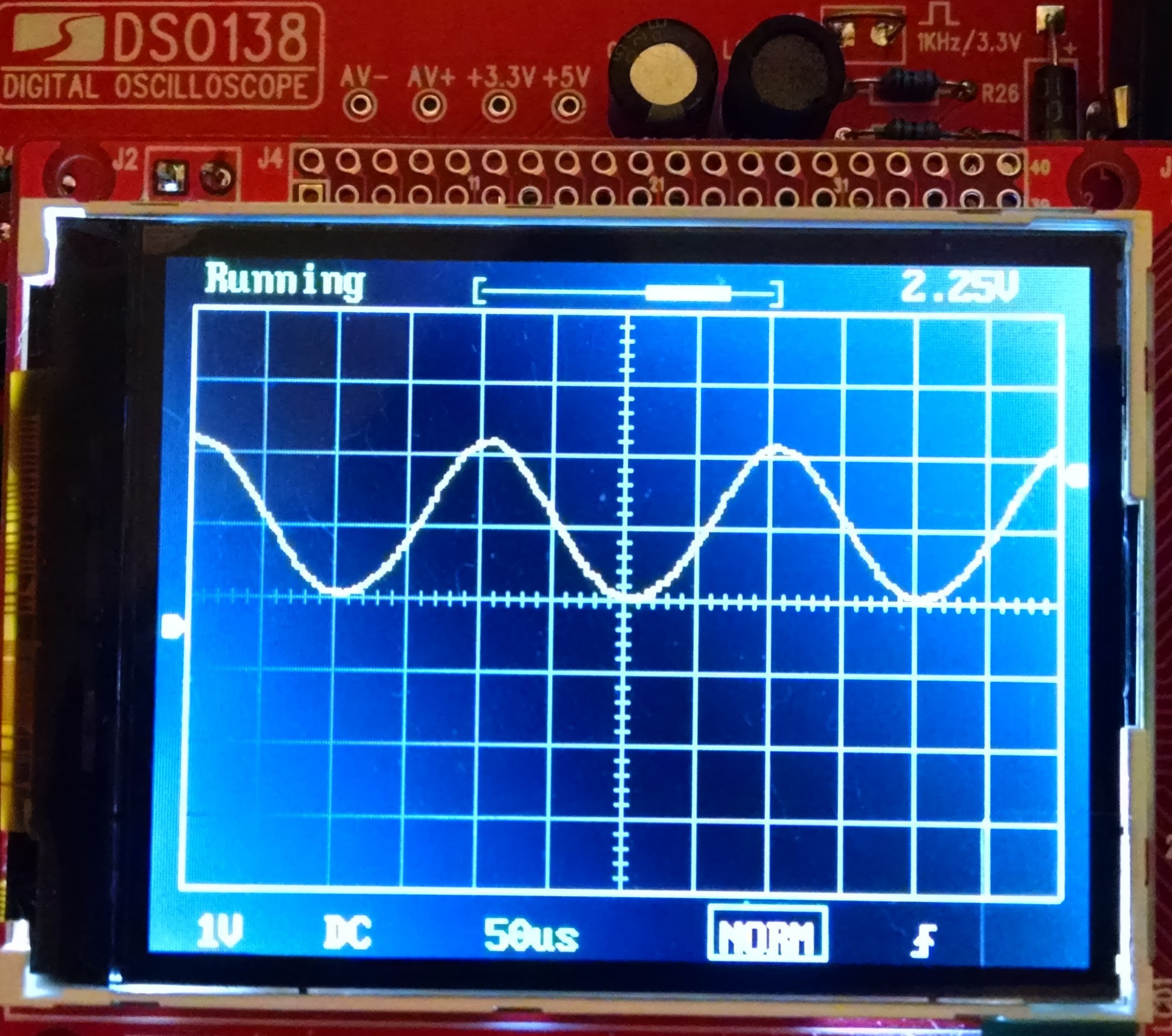
This makes me think that the laser receiver circuitry is producing a signal that the microcontroller can sample within it's (relative to the speed of light) limited processing clock speeds. The next photo is of the sine wave when the laser is pointing at a wall 1.8m away (by pressing the READ button once).
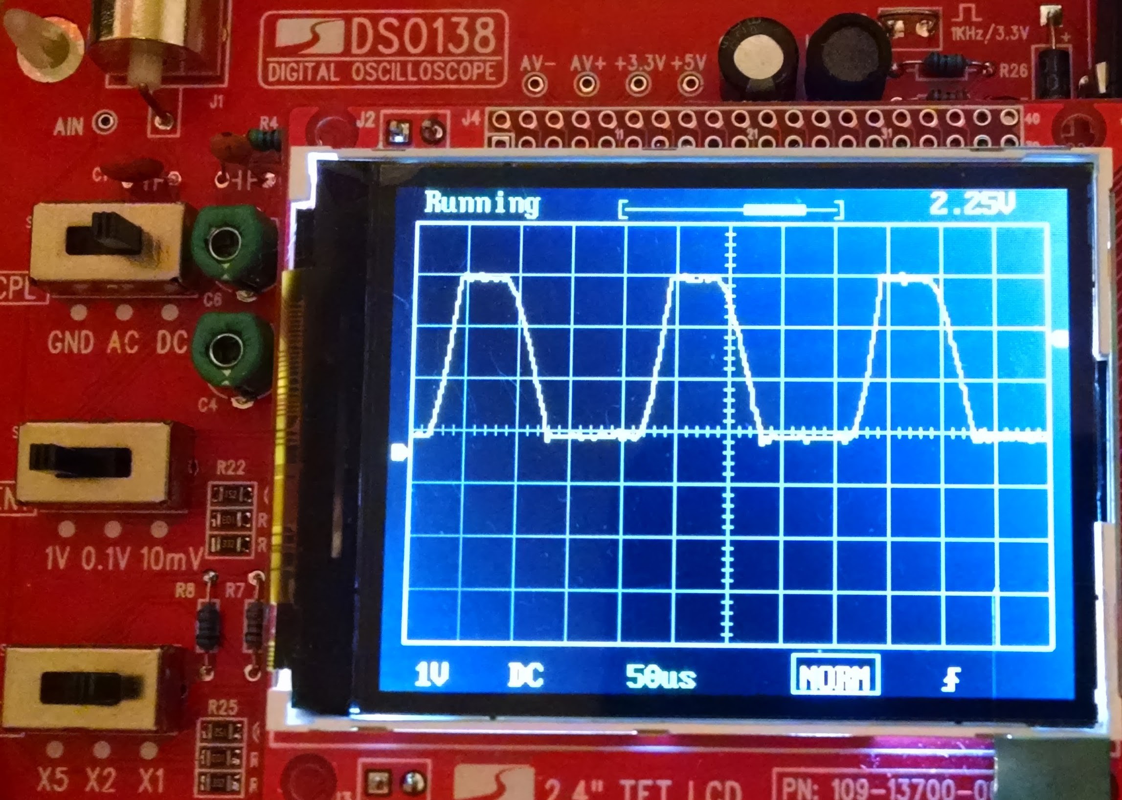
Then if I put my hand about 20cm in front of the beam/lens we get this higher voltage amplitude signal which is significantly clipped:
I don't know how the microcontroller is extracting the data it needs to perform a ranging calculation from this signal but I hope someone else out there could suggest a possible method and way to test if it works for a different microcontroller.
Finally, to be more confident that this is a received signal rather than a microcontroller-generated command signal, I covered up the lens:
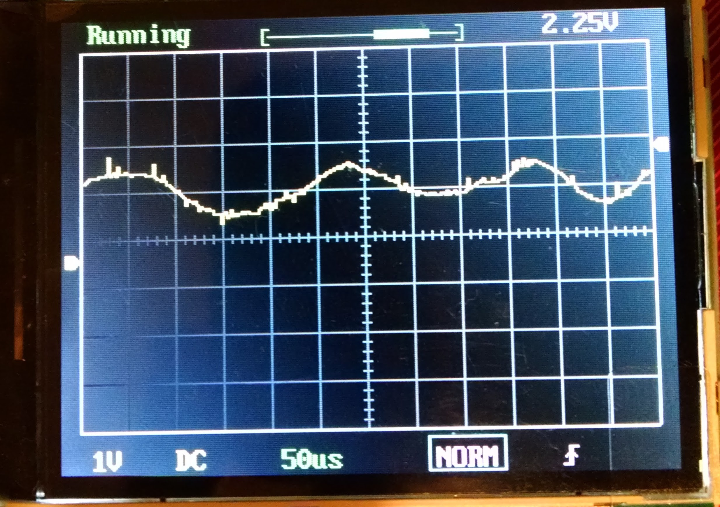
This captured image doesn't articulate the noise/random walk of the trace and I think it's a good enough indication that we are dealing with a signal from the laser receiver rather than the microcontroller.
I'd really like help here for ideas about what to do with this signal but the two mystery pads on the array are dragging me back to the search for a serial line on this microcontroller for debugging/firmware.
Discussions
Become a Hackaday.io Member
Create an account to leave a comment. Already have an account? Log In.
Myself I'm also trying to get a full understanding of the concept. Interferometry works with interference of the light waves themselves, so at extremely short wave lengths, so yes, phase shift is not unique in interferometry over even very short distances. However, as long as the phase shift is less than one period over the measuring range, the phase shift should be unique. That's where the power modulation comes in. In one period of, let's say, 1 microsecond, the light travels 300 000 000m/s * 0.000001s = 300 meters. Also, measuring at multiple modulation frequecies and at a fixed point in time can yield a set of equations that uniquely determine the phase shift. Maybe that's the reason of the ADC connection. (Actually, I made a miscalculation in my previous comment and I would expect the frequencies to be much higher. A distance of twice the range, i.e. 80 meters, coincides with one period at 3.75MHz. For the multiple frequencies approach, lower frequencies may however be sufficient.)
Are you sure? yes | no
Thank you gerbenrypkema! What a great resource. I have yet to fully understand the concept and which mode the UT390B+ is using because some of the interferometry description seems to more closely match what I see when I move the target distance - ie the phase shift isn't unique for any given distance as far as I can tell.
As this is a comparison technique with the power modulation signal, I shall see if I can trace that either from the diode or STM32F pins. I find it interesting that the laser receiver output is going straight into the ADC as I would have thought that a hardware phase comparator would be a good approach. Of course, if the phase shift isn't unique along the usable range (eg the interferometry method) the raw signal might be required to determine the absolute distance.
Are you sure? yes | no
It looks like it uses a sine modulated laser beam to determine the phase shift. This is a measure for the time delay between sent and received signal. See https://www.rp-photonics.com/phase_shift_method_for_distance_measurements.html . If I read the oscilloscope well, the frequency is about 5MHz, which makes sense as the wave length is then 60m, which is in the same order as the range of the device.
Are you sure? yes | no