Simon Merrett
-
Start
07/20/2016 at 00:46 • 0 commentsHi, I hope the mere initialisation of this project will encourage people to share what they know about the UT390B+. It's cheaper than the UT390B so if it can be hacked for microcontroller communication, there would probably be plenty of people keen to use it. All dismantling of your devices is at your own risk!
Firstly, take of the battery compartment to get right inside. There is one screw visible, one under a QC sticker inside the battery bay and one under the laser hazard sticker on the back of the UT390B+ (which by now should be facing you, just above the battery compartment. Remove the stickers and take all three screws out.
Now I wasn't sure how to separate the enclosure pieces but it appears that the front and back are still held together once the screws have been moved by a firm press-fit grey plastic band all round the optics at the front of the UT390B+. I pulled the two halves apart and the front ring suddenly popped off unharmed. I can't really see a less risky (of breaking the grey ring) way of doing this.
Inside is a flat flex cable from the main PCB (mounted in the back half of the case) to the button pcb (mounted in the front half). This was instantly pulled out of the ZIF connector on the button PCB when the two halves snapped apart but it looks unharmed.
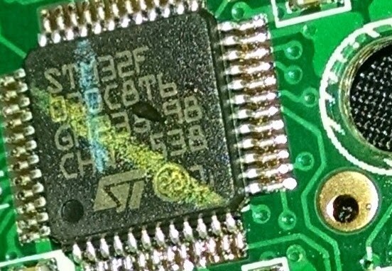
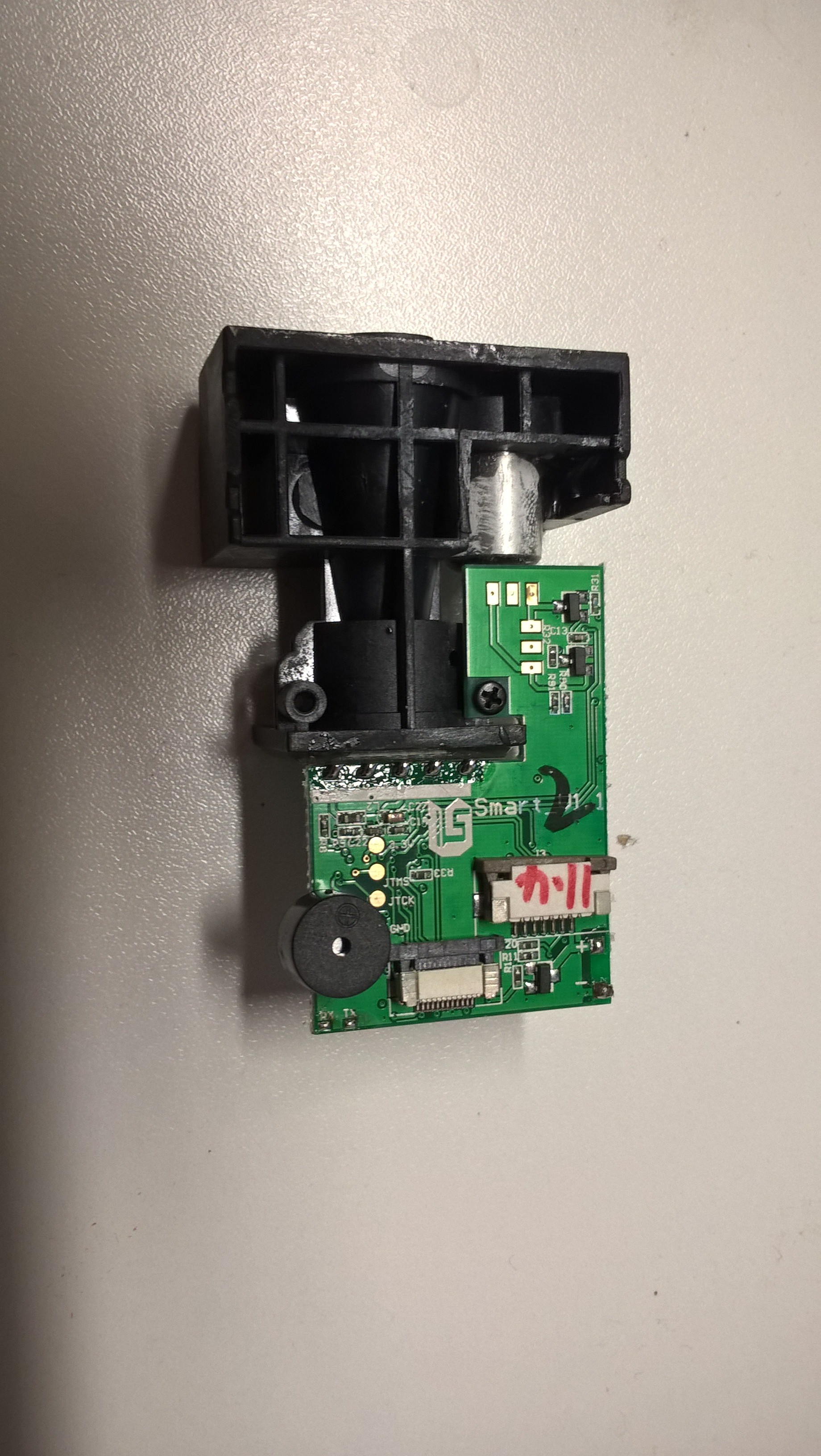
We can now see the main processor (looks to be STM32F 030CBT6 - not sure how many digits on the chip are required to ID), the screen, piezo buzzer, laser diode and laser optics. The laser optics looks like a large (10-15mm) lens with two smaller lenses moulded into one side of it. I hope someone can determine which method of ranging this device uses (I know that's been asked over at Instructables).
If we remove the PCB (two small screws), only the two power wires are connecting it to the case. Look underneath and there are the five pads which are visible in the battery bay and two prominent pads labelled (tantalisingly) RxD and TxD. Unfortunately, they don't appear to be recognisable serial contacts.
Not far from the RxD and TxD pins is a single via which goes all the way through. My cheapo DSO138 oscilloscope showed a nice sine wave off this pin when the laser was firing. Maybe that'll help those wondering what method this device uses to determine distance.
More soon, including pictures. Please get involved if you have a UT390B+ and have ideas about getting the external comms working.
-
Brick wall?
07/21/2016 at 13:56 • 0 commentsLast night I spent ages getting nowhere. Software serial on an Arduino Uno connected to TxD and RxD got nowhere.
My only small consolation was that I found the 4 pads near the keypad FFC/ZIF connector on the main PCB were actually breakouts of the buttons and have a pull up resistor on them. When a button was pressed, the line is pulled low. This means it would be easy to remove the keypad and send logic level button presses from a microcontroller. Others have discussed intercepting the LCD display data stream to extract the digital readings if some form of serial communication can't be established.
The pads that are visible from the battery compartment are still intriguing - why would useless pads be designed into both the PCB underneath AND the enclosure moulding? There's too much coincidence to write them off yet. Others think they've characterised the 5 pads as including VCC, GND and Reset/reboot, with two strange pads remaining.
One of these is pulled high and the other is pulled low. Does anyone know of an electrical communication protocol which has these characteristics at rest? Perhaps an industrial protocol designed for long wire transmission distances, with a balanced signal, such as RS485 uses.
An idea I've had today is that the sine wave might not be the input to the laser driver and there's a small (but hopeful) chance that it's a feed from the laser receiver into the main STM32F controller. I'll see if I can find out more later.
-
Glimmers
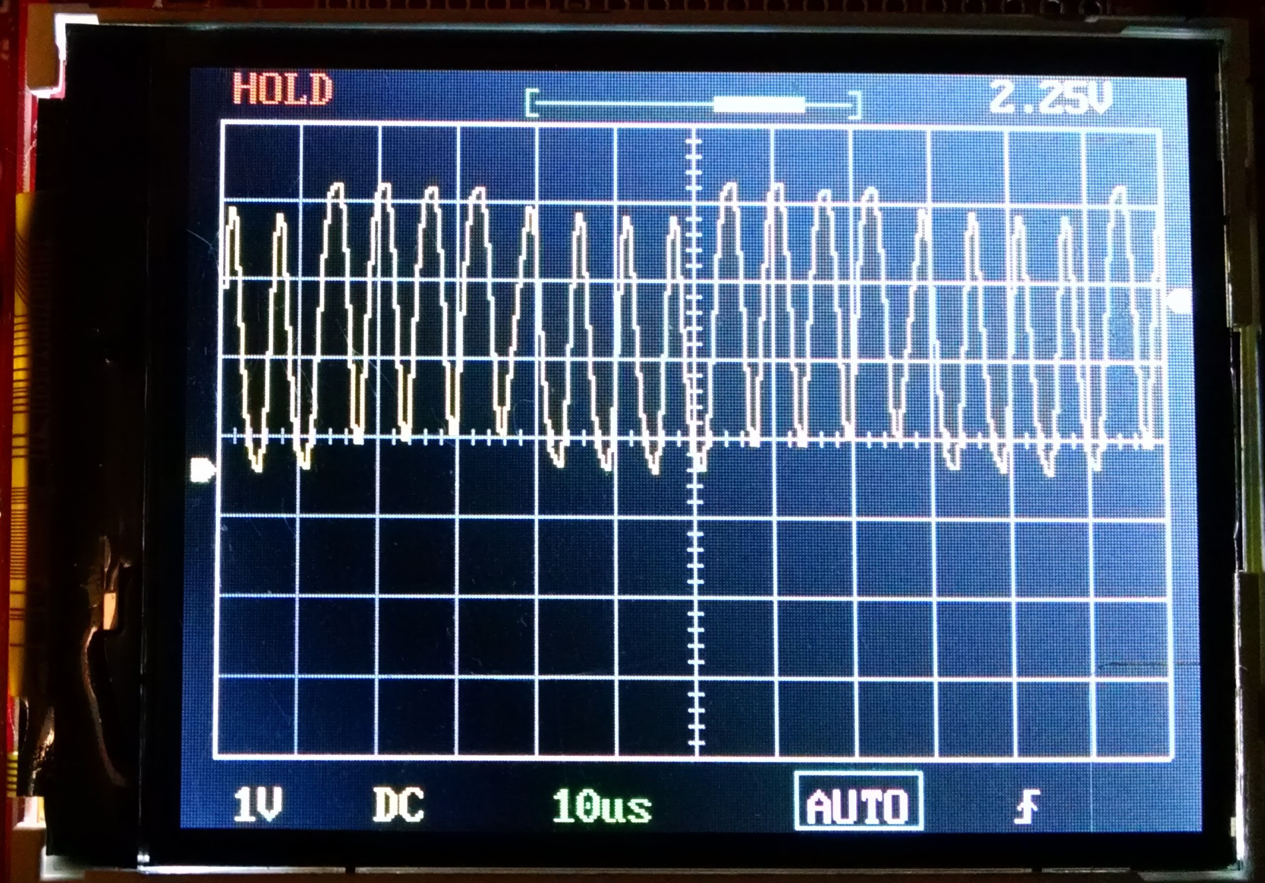
07/21/2016 at 22:59 • 3 commentsI have found a few points of light, mostly around the lone via which gives out a sine wave when the laser is firing. Initially, I assumed this was some ramp-esque control signal to the laser but the photos below suggest that it's actually the output from the laser receiver (and it's conditioning circuitry) into the microcontroller. The first photo is of the pad/via in the bottom right hand corner of the photo.
![]()
When I checked, this is connected to pin 11, PA1 on the LFQP 48 package and the additional function of that pin is... ADC_IN1.
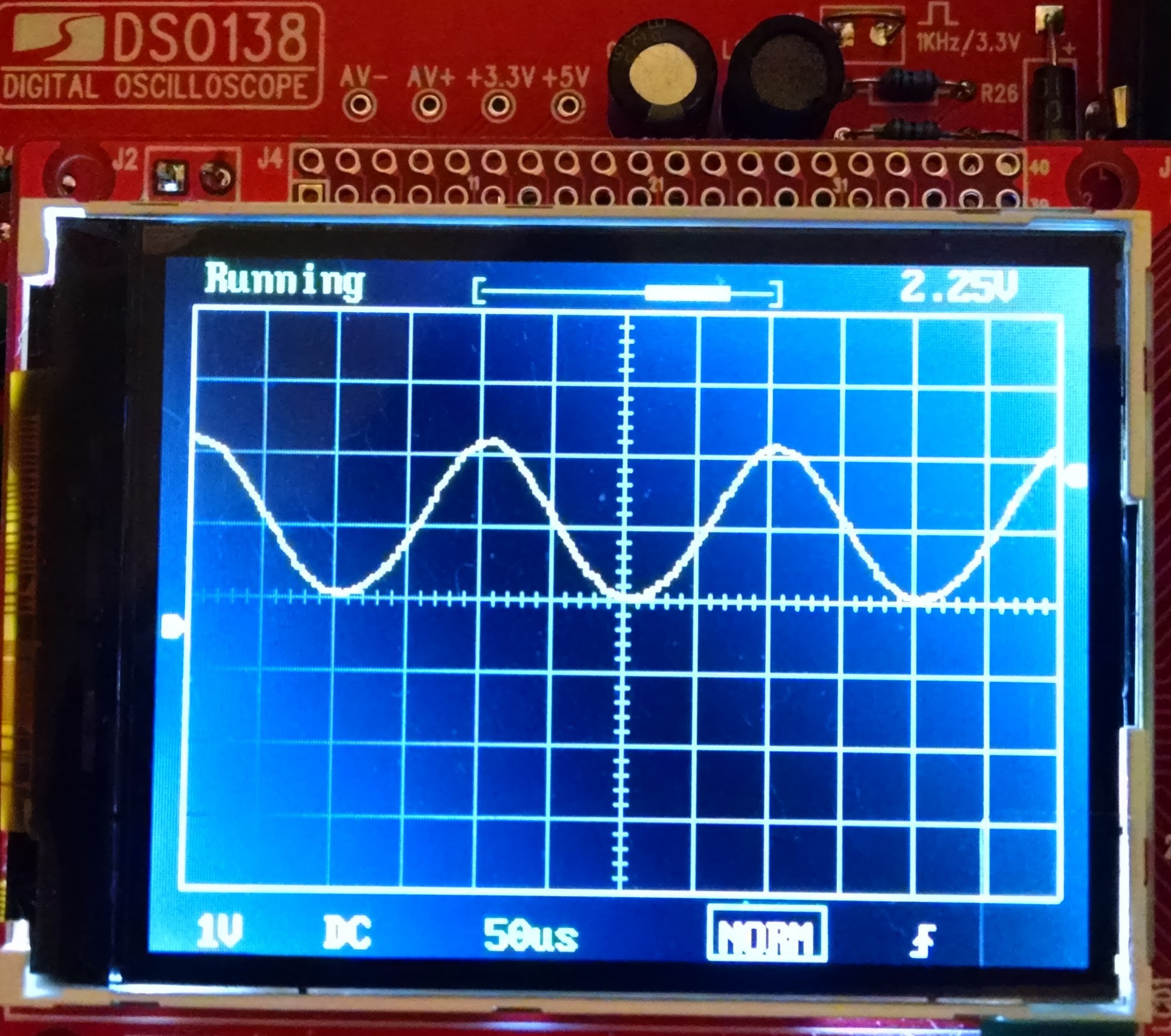
This makes me think that the laser receiver circuitry is producing a signal that the microcontroller can sample within it's (relative to the speed of light) limited processing clock speeds. The next photo is of the sine wave when the laser is pointing at a wall 1.8m away (by pressing the READ button once).
![]()
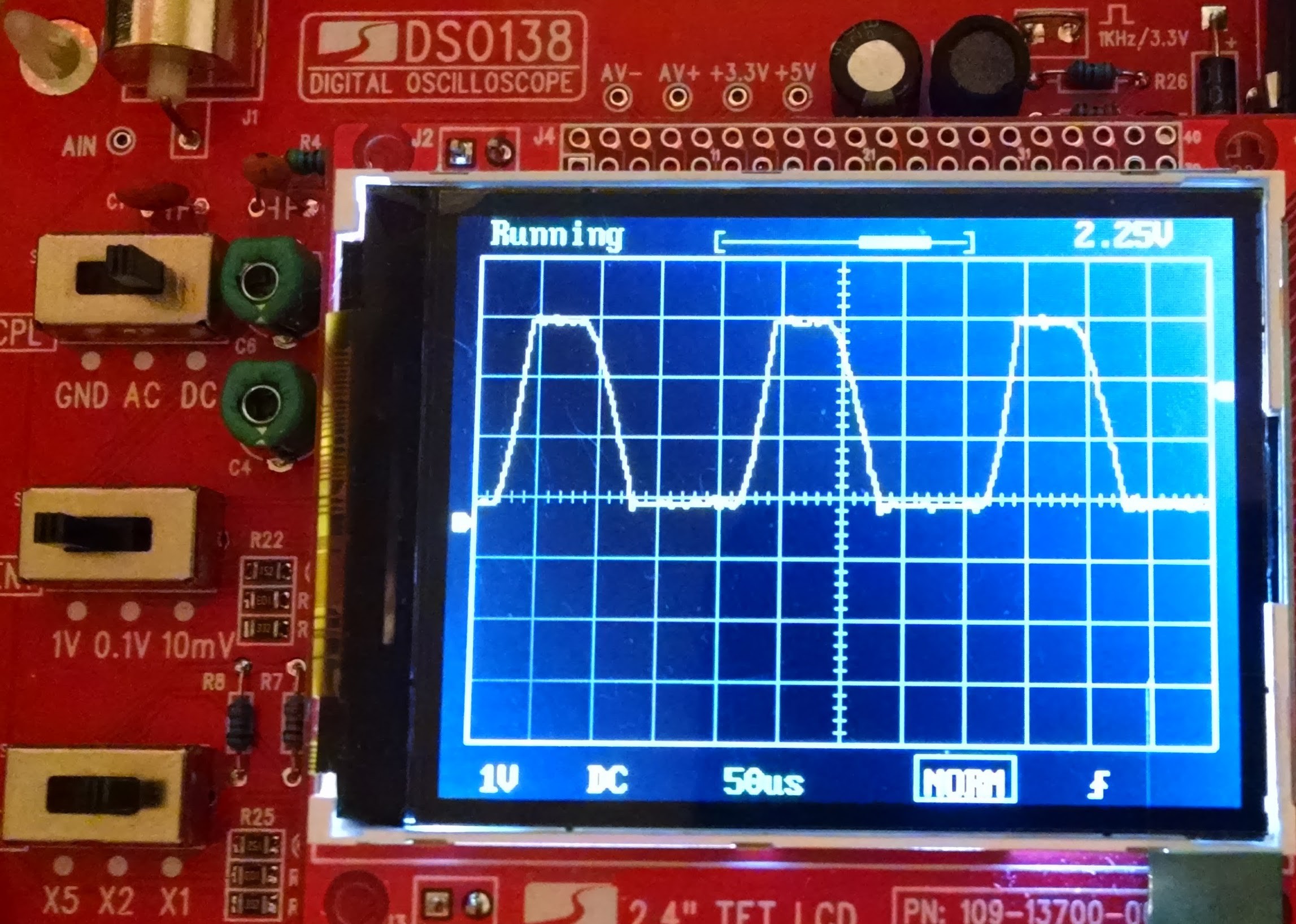
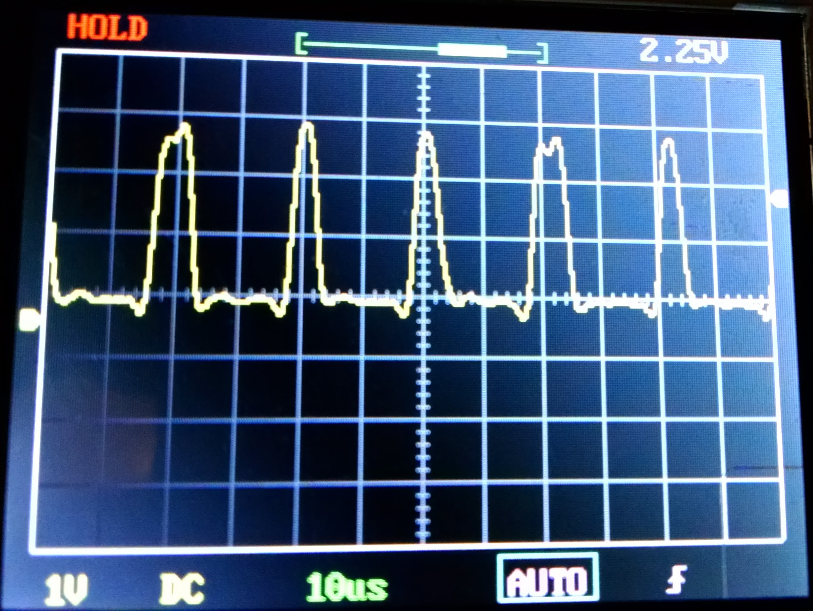
Then if I put my hand about 20cm in front of the beam/lens we get this higher voltage amplitude signal which is significantly clipped:
![]()
I don't know how the microcontroller is extracting the data it needs to perform a ranging calculation from this signal but I hope someone else out there could suggest a possible method and way to test if it works for a different microcontroller.
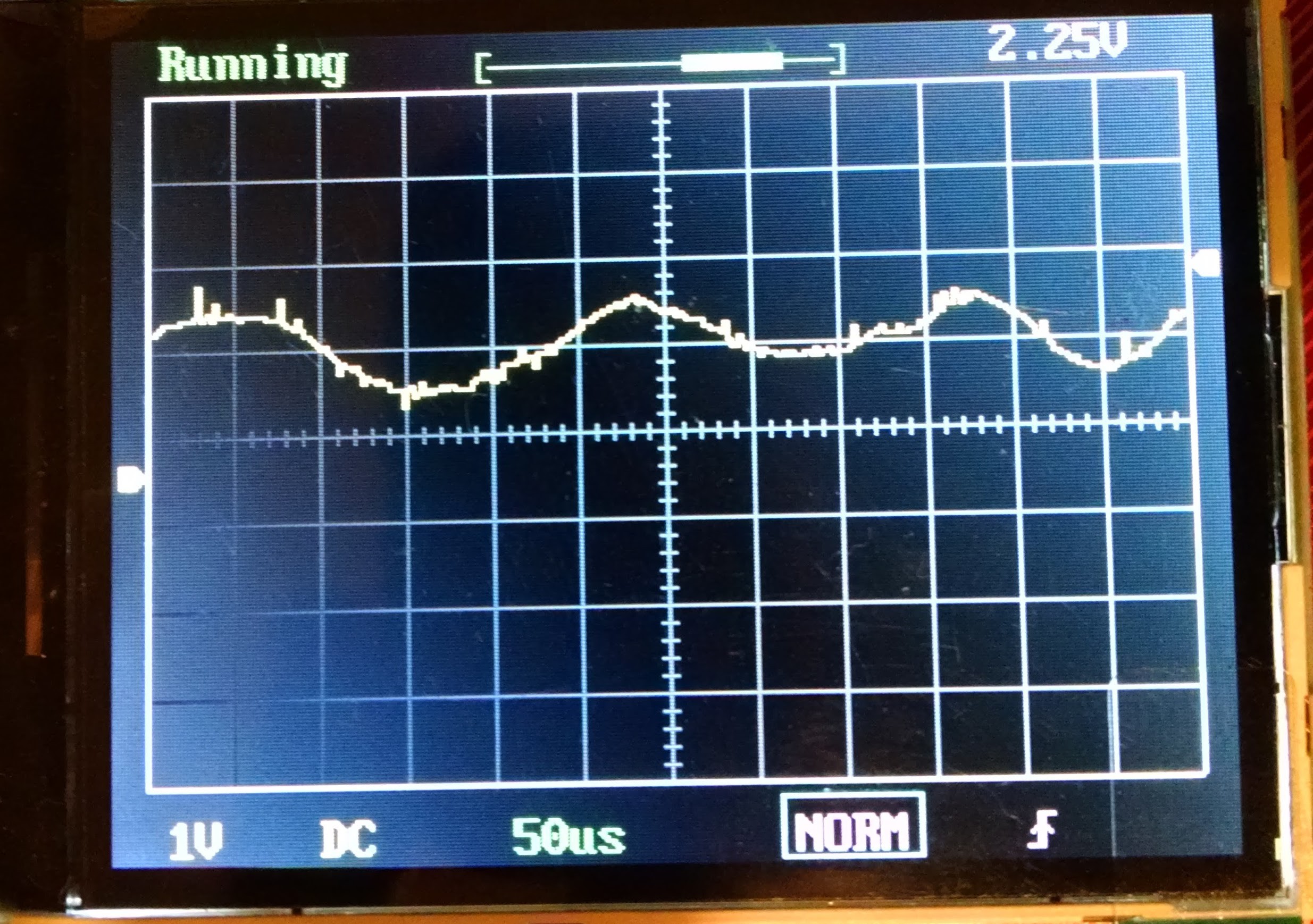
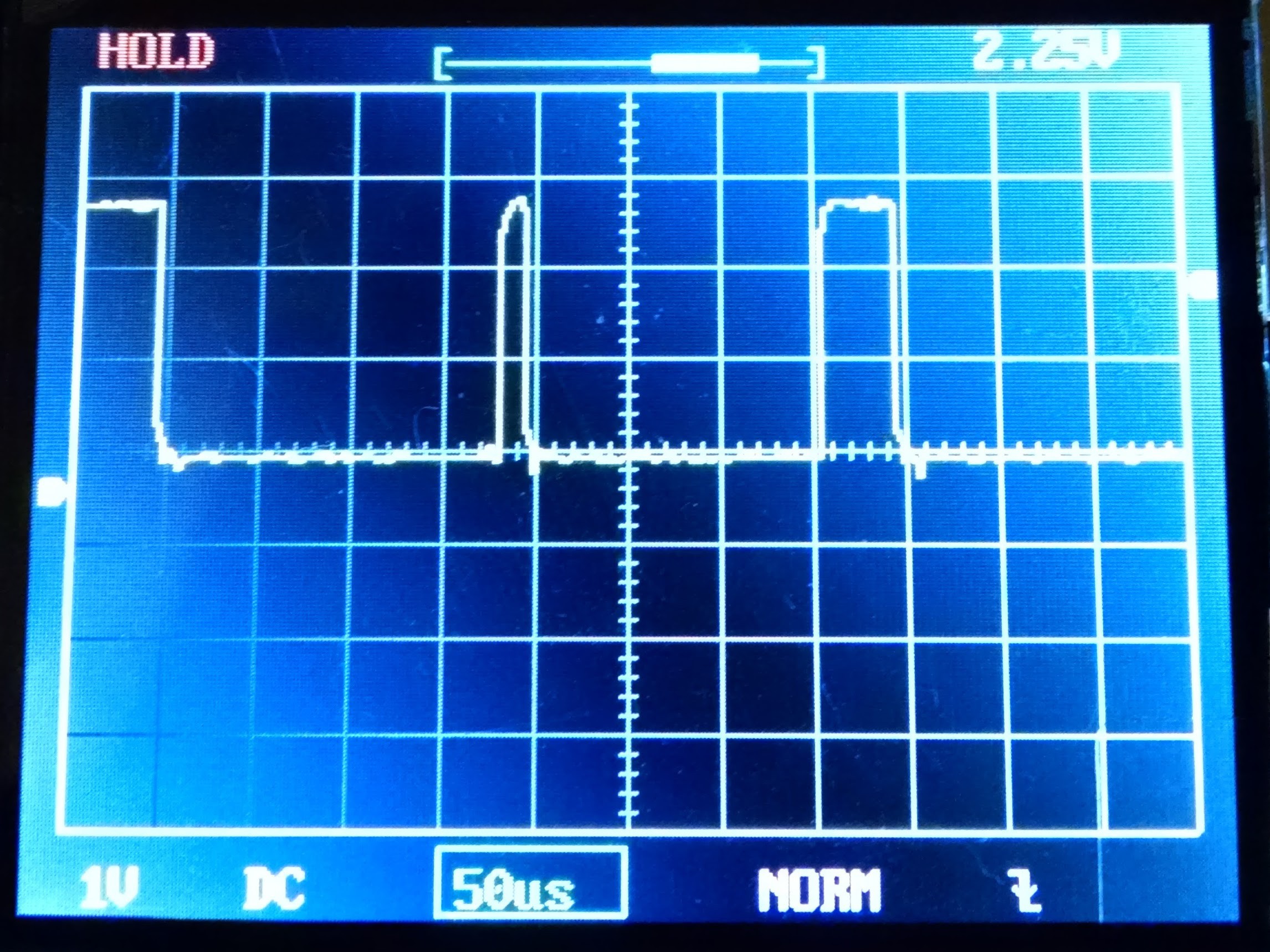
Finally, to be more confident that this is a received signal rather than a microcontroller-generated command signal, I covered up the lens:
![]()
This captured image doesn't articulate the noise/random walk of the trace and I think it's a good enough indication that we are dealing with a signal from the laser receiver rather than the microcontroller.
I'd really like help here for ideas about what to do with this signal but the two mystery pads on the array are dragging me back to the search for a serial line on this microcontroller for debugging/firmware.
-
SWD
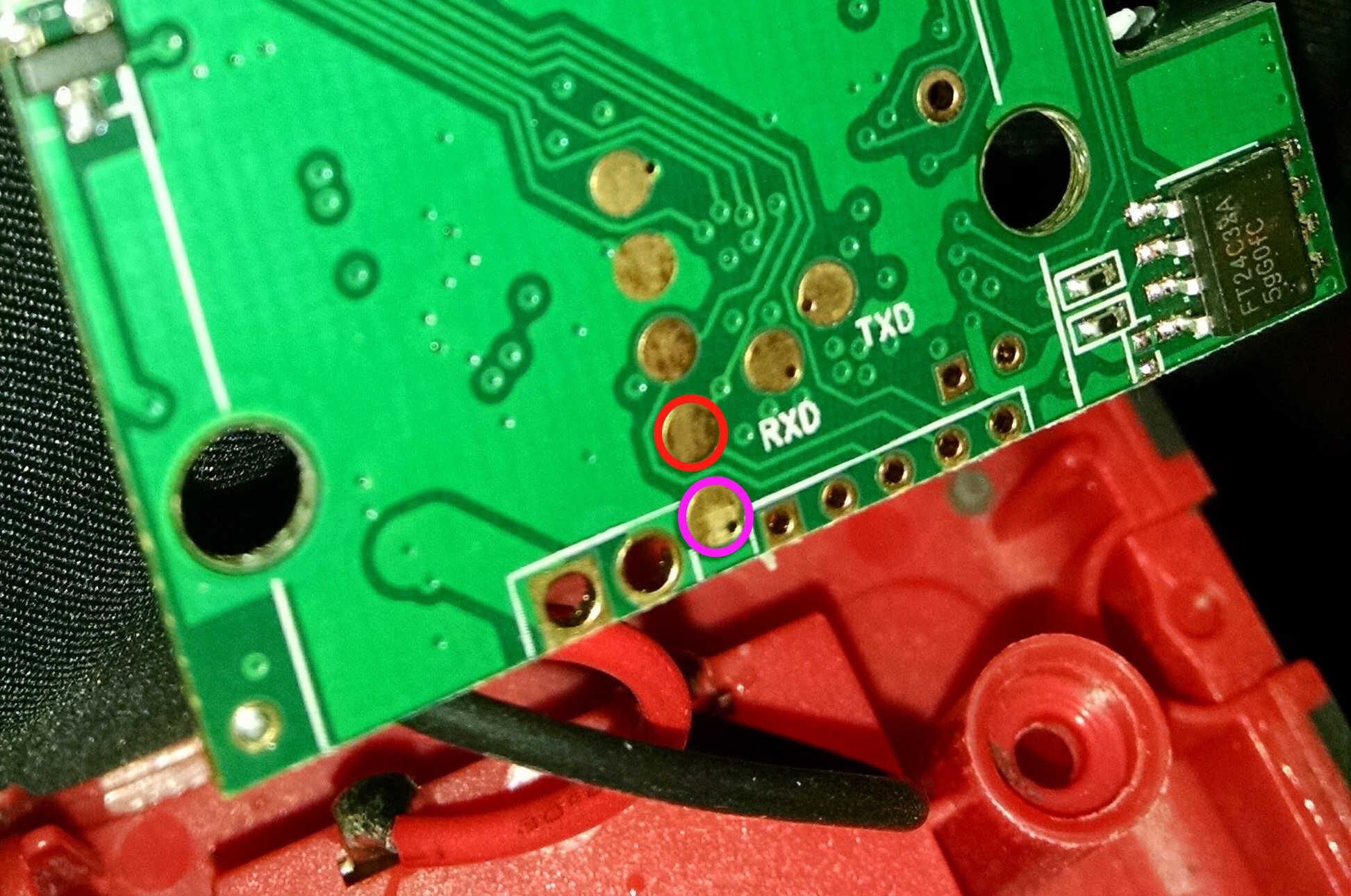
07/22/2016 at 07:42 • 0 commentsIt turns out that the two mystery pads at one end of the five which are exposed to through the battery bay are Serial Wire Debug lines, or SWD. I have only just heard of this term when I looked into the Mechaduino and how you need the SDW interface for loading the Arduino bootloader on the Atmel SAMD21 that they're using (same chip as in Arduino/Genuino Zero - good call Tropical Labs). I traced the pads ringed in the picture below with the multimeter and the pink one is connected to PA13 (SWDIO) and the red one is connected to PA14 (SWCLK).
![]()
I have yet to find out if we can talk to the STM32F via SWD but thought I'd let you know the latest finding. More to follow.
An idea: perhaps there are other chips on this board which have interfaces that would let us talk to the STM32F, like SPI or I2C (although slaves are unlikely to get very far). Datasheets ahoy!
-
Quick dump...
07/24/2016 at 21:34 • 0 commentsJust from probing while I was offline this weekend:
PA5 (Pin 15) is high frequency pulses, sine and carrier.
![]()
Also on that pin is SPI CLK and ADC_IN 5.
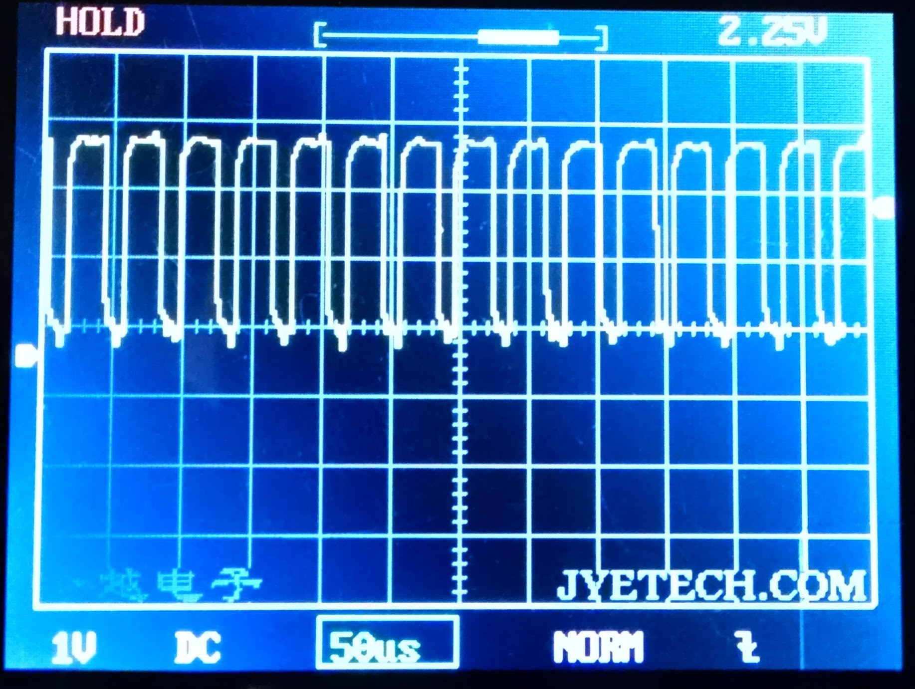
PA8 is giving out a 20 uSec period pulse (500 kHz) when the button is pressed. It's the only one I can see which has MCO as a function but it also does USART1 CLK. I presume this is the MCO output though:
![]()
PB7 is giving a short 20 uSec pulse, 150 uSec pause then 50 uSec pulse. It's SDA for I2C_1:
![]()
Meanwhile, PB6 is I2C_1 SCL and is producing a 40 uSec period pull down pulse @ 50% duty:
![]()
The I2C messes up the LCD when wires got shorted by my probe so I'm confident this is what it's being used for.
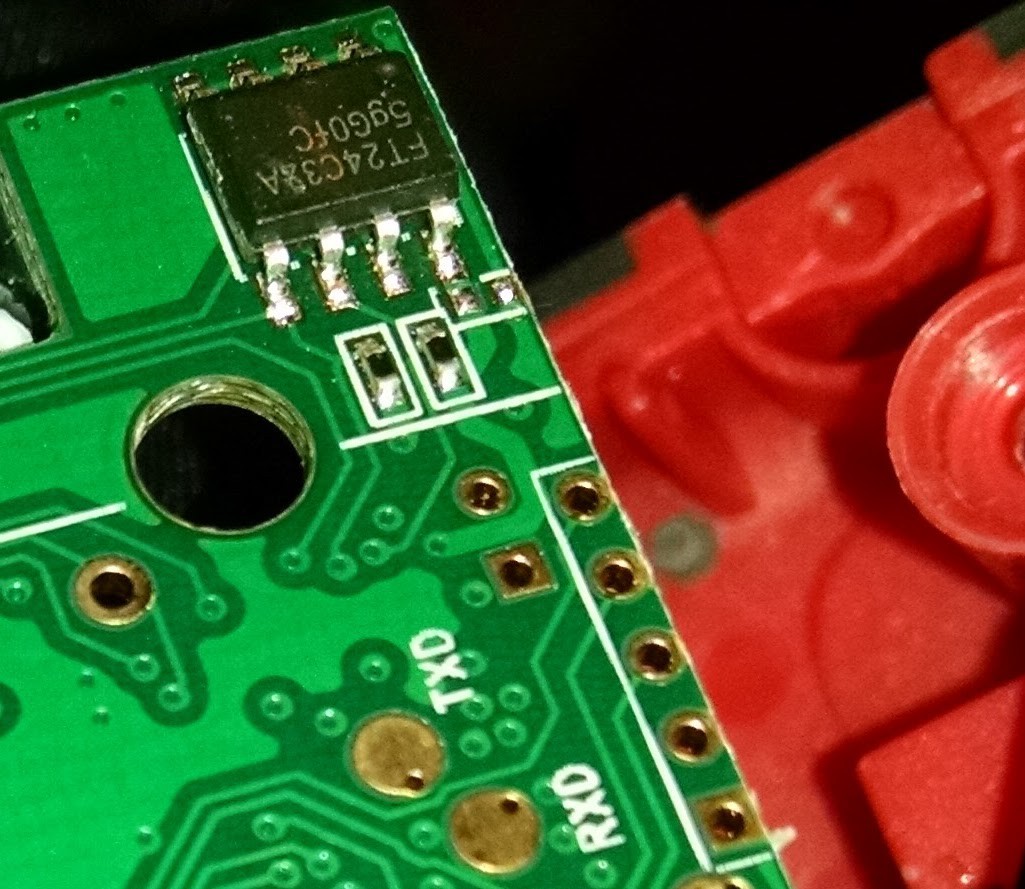
The FT24C32A chip is two wire serial EEPROM. Maybe i2c talking there too?
![]()
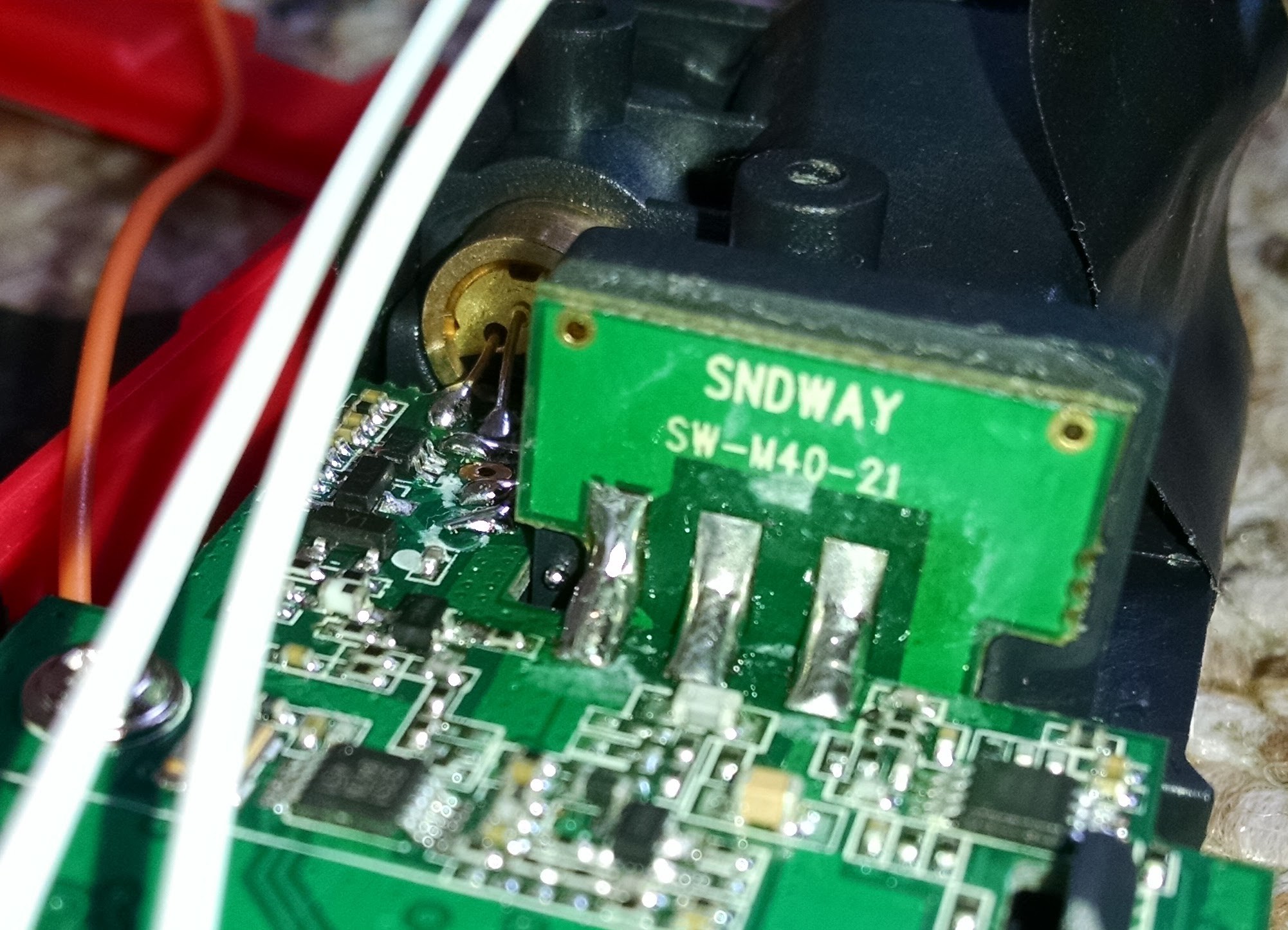
I have a feeling that the chips near the laser which have 5351 on are copies of the MAXIM 3.3V version of the 535 DAC. More checks required.
I've also emailed SNDWAY, who make the laser module, to see if they'll tell us the inputs/outputs from the module.
![]()
I'm not holding my breath as they also make their own laser range finder consumer products and it would be giving their secret sauce away somewhat.
Please chip in with ideas as I'm about to hit the limits of what I can do with this to get a useful distance measurement out of it!
-
More pin mapping
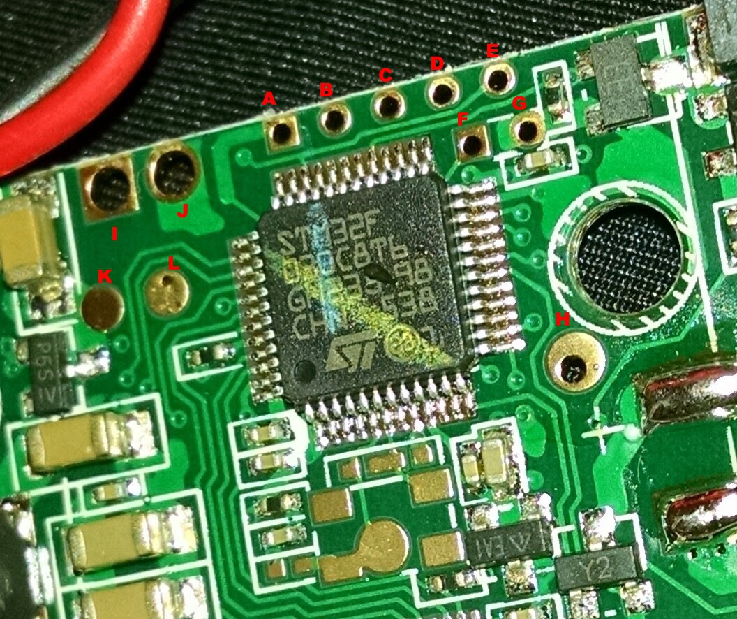
07/26/2016 at 20:43 • 0 commentsUsing this pad reference picture:
![]()
E = PA13, D=PA14: SWDIO & SWCLK, as mentioned before. C = NRST. B = GND. A = VDD.
I = VBAT. J = GND. K = VBAT. L = GND. H = ADC1_IN (Probably) as described in a previous log.
The I2C lines are where I might try next.
-
Fried
07/27/2016 at 23:59 • 0 commentsThink I've killed the STM32F. LCD isn't showing anything, there's a funny audible scratching sound when I press the laser firing button and even though the laser fires, I can't get anything useful out of the previously active pins. This is all after I tried soldering a jumper wire to all the exposed pads and there's a good chance some of them hit the 9V rail on my breadboard power supply.
Oh well. Perhaps time to try a different laser distance measurer. There's a Bosch PLR15 in the post...
-
Tried and gave up
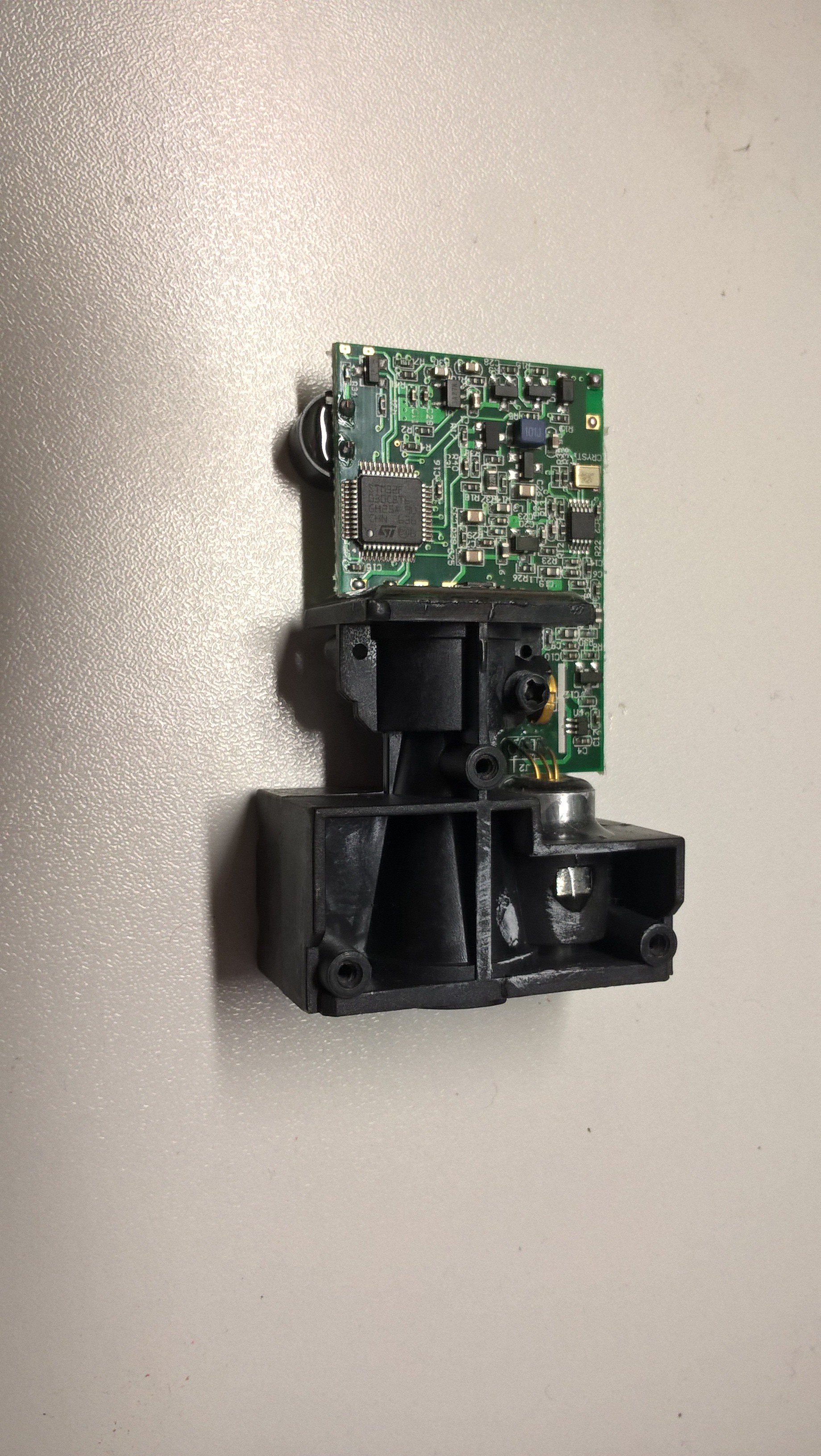
11/20/2016 at 18:04 • 6 commentsI tried to get some data out of a KKMOON branded laser range meter.
It's inside is from SNDWAY and looks basicly like the UNI-T UT390B+. Moreover there were some debug pads inside wired to RX and TX but they were dead.
First I did some measurements on different pins, like Simon did, but finally I gave up since it was too time consuming.
Now I have orded some other device beeing supposed to have an active RS232 port. So I will keep you informed if I have any news.
![]()
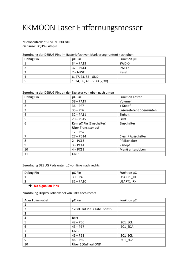
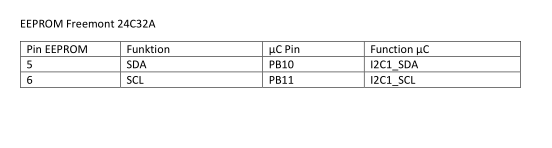
Moreover I attached the information I could find out about the pinning - it's written in German. Unfortunately I couldn't upload the pdf file.
![]()
![]()
-
Going deeper into schematic
11/30/2016 at 08:55 • 1 commentHi everyone.
Simon found than small IC placed near laser diode and APD photodiode is Si5351. It is dual PLL clock generator, controlled by I2C bus. It can generate two different frequencies from 8 kHz to 160 MHz.
I think that si5351 generates two high (>100 Mhz) but close frequencies. One of them is used to modulate laser, another - to modulate APD photodiode power.
These two frequencies are mixed at APD and the resulting low frequency is amplified by sgm8592 IC. The amplified signal (there were photos of this signal at oscilloscope) is analysed by MCU.
So, I think that it is possible to capture I2C signals and calculate used frequencies. After that it is possible to write new firmware for STM32, which would analyse resulting signal. That way can give an advantage - it is possible to create less accurate (~10 mm) but faster (>10 Hz) rangefinder.
Now I'm waiting for delivery of Chinese rangefinder module, it's construction is very similar to UT390+ (it has si5351 installed).
I want to do it's full reverse engineering, and write my own code for rangefinder's STM32.
I hope that code will be suitable for UT390+ too.
-
Another device
01/12/2017 at 19:09 • 1 commentHi everyone,
meanwhile I got some samples from another device.
It's brand is "NSCE Laser" and Type is "NS-XX"
XX stands for Number 20 to 60 which tells the maximum ranging distance.
With the device I got the description of the communication protocol for a included serial interface. The device works at 5V and communications works with an arduino.
![]()
![]()
On the last picture you can see RX and TX on the left corner.
It uses also the STM 32F MCU.
I'm thinking of ordering a bigger number of the device if someone else is interestet in I could organize a collective order.
The only thing is that I'm living in Germany, so I don't know if it makes sense that someone outside Europe takes part, although I would foreward the devices to other countrys.
Peek inside UNI-T UT390B+
Much cleverer people hacked the orginal UT390B laser range finder but no-one seems to have published what we know about the UT390+.